background image

68

107672-01 - 7/17

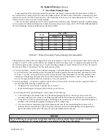
Gas piping to the boiler must be sized to deliver adequate gas for the boiler to fire at the nameplate input at an inlet 

pressure between the minimum and maximum values shown in Table 8.2. When sizing, also consider other existing 

and expected future gas utilization equipment (i.e. water heater, cooking equipment).  For more information on gas line 

sizing, consult the utility or the 

National Fuel Gas Code, 

NFPA54/ANSI Z223.1, and/or CAN/CSA B149.1 

Natural 

Gas and Propane Installation Code.

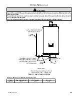
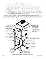
Figure 8.1 shows typical gas piping connection to the boiler. A sediment trap must be installed upstream of all gas 

controls. Install the factory provided manual shut-off valve outside the jacket with a ground joint union as shown.  

All above ground gas piping upstream from manual shut-off valve must be electrically continuous and bonded to a 

grounding electrode.  Refer to 

National Electrical Code,

 NFPA 70.

The boiler and its gas connection must be leak tested before placing the boiler in operation. When doing this, the boiler 

and its individual shut-off must be disconnected from the rest of the system during any pressure testing of that system 

at pressures in excess of 1/2 psi (3.5kPa). When pressure testing the gas system at pressures of 1/2 psi (3.5kPa) or less, 

isolate the boiler from the gas supply system by closing its individual manual shut-off valve.  Locate leaks using an 

appropriate combustible gas non-corrosive leak detector solution.

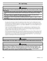
VIII.  Gas Piping

 Warning

Explosion Hazard.  Failure to properly pipe gas supply to boiler may result in improper operation or leaks of 

flammable gas. 

Gas supply to boiler and system must be absolutely shut off prior to installing or servicing boiler gas piping.
Always assure gas piping is absolutely leak free and of the proper size and type for the connected 

load.
Use a thread compound compatible with liquefied petroleum gas.  Failure to use proper thread 

compounds on all gas connectors may result in leaks of flammable gas.
If inlet pressure is above 1/2 psig (3.4 kPa) an additional gas pressure regulator is required.  Consult 

gas supplier.
Size corrugated stainless steel tubing (CSST) to ensure proper capacity and minimize flow restrictions.  


DANGER

Explosion Hazard.  Do not use matches, candles, open flames or other ignition source to check for leaks.


Warning

If gas pressure in the building is above ½ psig (3.4 kPa), an additional gas pressure regulator is required.  

Using one additional regulator for multiple gas appliances may result in unsafe boiler operation.  The 

additional regulator must be able to properly regulate gas pressure at the input of the smallest appliance.  

If the regulator can not do this, two or more additional regulators are required.  Consult regulator 

manufacturer and/or local gas supplier for instructions and equipment ratings.

Summary of Contents for K2WT-080B

Page 1: ...ormation consult a qualified installer service agency or the gas supplier This boiler requires a special venting system Read these instructions carefully before installing 9700609 As an ENERGY STAR Pa...

Page 2: ...stantial property damage CAUTION Indicates a potentially hazardous situation which if not avoided may result in moderate or minor injury or property damage WARNING Indicates a potentially hazardous si...

Page 3: ...disconnect any components of this boiler without positively assuring the water is cool and has no pressure Always wear protective clothing and equipment when installing starting up or servicing this...

Page 4: ...ls carbon monoxide nitrogen oxides and or other toxic or harmful substances that can are hazardous to health and life and that are known to the State of California to cause cancer birth defects and ot...

Page 5: ...Polyflue Vent Systems 56 H Assembly of Centrotherm InnoFlue Vent Systems 60 I Assembly of Stainless Steel Vent Systems 64 J Condensate Trap and Drain 66 K Removing An Existing Boiler From Common Chim...

Page 6: ...ly with combustion air sup plied from outdoors It is not designed for use in gravity hot water systems or systems containing significant amounts of dissolved oxygen I Product Description 15 A SEE TABL...

Page 7: ...on of this boiler depends upon installation by a professional heating contractor in strict accordance with this manual and the requirements of the authority having jurisdiction In the absence of an au...

Page 8: ...e minimum clearances shown in Figure 4 1 These clearances apply to combustible construction as well as non combustible walls floors ceilings and doors 2 Note the recommended service clearances in Figu...

Page 9: ...07672 01 7 17 Figure 4 1 Minimum Clearances To Combustible Construction IV Locating the Boiler continued LEFT SIDE CLEARANCE MAY BE REDUCED TO 1 2 HOWEVER RELIEF VALVE MUST REMAIN IN SAME SPACE AS BOI...

Page 10: ...e holes A and B Make sure that the horizontal centerline of these holes is level Holes C and D may also be drilled at this time or after the boiler is hung on the wall If the 5 16 x 2 lag screws are u...

Page 11: ...11 107672 01 7 17 Figure 5 1 Wall Layout Mounting Hole Location V Mounting The Boiler continued...

Page 12: ...12 107672 01 7 17 Figure 5 2 Boiler Mounting Bracket Installation Boiler Wall Mounting V Mounting The Boiler continued...

Page 13: ...ther appliances provide adequate air for combustion and or ventilation air in accordance with the manufacturer s installation manual or applicable code VI Air for Ventilation WARNING Outdoor combustio...

Page 14: ...y as permitted in this manual All PVC must be listed to ASTM D2665 At least 30 of CPVC pipe and at least one CPVC elbow must be installed between the boiler s vent connection and the PVC pipe Use of f...

Page 15: ...15 107672 01 7 17 Figure 7 0c Split Venting VII Venting A Vent System Design continued Figure 7 0a Horizontal Twin Pipe Figure 7 0b Vertical Twin Pipe BOILER...

Page 16: ...addition to the first 90 elbow If more elbows are desired the maximum allowable vent length must be reduced by the amount shown in Table 7 1B for each additional elbow used Termination fittings are n...

Page 17: ...A a To properly install attenuator insert approximately a 9 length CPVC pipe in vent adaptor b Fit a 3 CPVC coupling on length of pipe Glue coupling to pipe using a field supplied cement and primer th...

Page 18: ...lengths shown in Tables 7 5 7 13 and 7 21 6 Clearances to Combustibles Maintain the following clearances from the vent system to combustible construction Vent 1 4 also observe clearances through both...

Page 19: ...C PVC pipe design the vent system shall allow 3 8 of thermal expansion for every 10ft of CPVC PVC pipe The boiler will always act as an anchor to one end of the vent system If at all possible select a...

Page 20: ...20 107672 01 7 17 VII Venting A Vent System Design continued Figure 7 3 Expansion Loops for CPVC PVC Pipe Figure 7 3b Figure 7 3a Figure 7 4 Wall Penetration Clearances for PVC Vent Pipe Figure 7 3c...

Page 21: ...ay not be snorkeled Terminal Option B Ipex Low Profile Terminal Acceptable for Vent Options 1 2 This terminal is shown in Figure 7 7 If the terminal is oriented vertically alternate orientation shown...

Page 22: ...ISEP0239 w screen ISEP03 or ISEP0339 w screen Intake Elbow w screen Note 3 Elbow w screen Note 3 Elbow w screen Elbow w screen Elbow w screen Elbow w screen Elbow w screen Elbow w screen Terminal Opt...

Page 23: ...rs and relief equipment Do not install vent terminal over this equipment In Canada refer to B149 1 Installation Code for clearance to meters regulators and relief equipment Do not locate the vent term...

Page 24: ...quirements Unique to Horizontal Twin Pipe Venting Systems continued PITCH INTAKE AWAY FROM BOILER IF POSSIBLE BOILER ROOM PVC AIR INTAKE PIPE CPVC VENT PIPE FIRST 30 ELBOW PVC VENT PIPE PITCH VENT PIP...

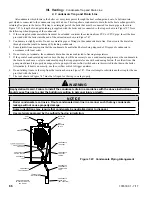
Page 25: ...ravent PolyPro Horizontal Venting with Concentric Terminal Vent Options 3 4 Terminal Option F VII Venting B Design Requirements Unique to Horizontal Twin Pipe Venting Systems continued PITCH INTAKE AW...

Page 26: ...tal Twin Pipe Venting Systems continued Note Air intake termination not shown Figure 7 11 Location of Vent Terminal Relative to Windows Doors Grades Overhangs Meters and Forced Air Inlets Two Pipe Sys...

Page 27: ...ns is generally recommended for both terminations Two rodent screens are included within the available 2 and 3 vent kits or can be fabricated from 1 2 stainless steel mesh screen Rodent screens and ar...

Page 28: ...PPS 36B w Screen 2PF 10UV or 2PF 39UV w Screen 3PF 10UV or 3PF 39UV w Screen ISEP02 or ISEP0239 w Screen ISEP03 or ISEP0339 w Screen Intake 180 Elbow w Screen 180 Elbow w Screen 180 Elbow w Screen 180...

Page 29: ...t Vent Manufacturer s PN for Flex Termination Components Required 2PPS VFT 2PPS BV 2PPS FLEX 3PPS VFT 3PPS BV 3PPS FLEX IFBK02 IAWP02B IFBK03 IAWP03B Specify size of B vent e g 2PPS BV6 is for use wit...

Page 30: ...from an outside wall see Section VII D for additional details All venting is Polypropylene supplied by the vent manufacturer shown in Table 7 13b The portion of this venting within the B vent is flex...

Page 31: ...rotherm InnoFlue Flex 2 0 ft 2 Selkirk Polyflue 2 0 ft 3 DuraVent PolyPro Flex 2 0 ft 3 Centrotherm InnoFlue Flex 2 3 ft 3 Selkirk Polyflue 2 3 ft 3 Duravent FasNSeal Flex 1 0 ft B Vent Air Chase 1ft...

Page 32: ...C PVC Venting Vent Options 10 11 Terminal Option H Figure 7 16 Vertical CPVC PVC Venting with IPEX Concentric Vent Terminal Vent Options 10 11 Terminal Option I J VII Venting C Design Requirements Uni...

Page 33: ...otherm InnoFlue Vertical Single Wall PP Venting Vent Options 12 17 Terminal Option H Figure 7 18 Duravent PolyPro Vertical Venting with Concentric Terminal Vent Options 12 13 Terminal Option J VII Ven...

Page 34: ...Venting C Design Requirements Unique to Vertical Venting Systems continued Figure 7 19 Duravent PolyPro B Vent Air Chase System Vent Options 18 19 Figure 7 20 Centrotherm InnoFlue B Vent Air Chase Sys...

Page 35: ...e Terminal Location Observe the following limitations on the intake terminal location also see Figures 7 22 7 23 7 24a and 7 25a The bottom of all terminals must be at least 12 above the normal snow l...

Page 36: ...lexible polypropylene vent installation is not permitted through any of the adjacent flues Asphyxiation Hazard Flexible stainless steel vent must be installed only in an UNUSED chimney flue A chimney...

Page 37: ...t 135ft 180 135ft 135ft 135ft Rigid Vent Terminals Vent Coupling w Screen Coupling w Screen 2PPS 12B or 2PPS 36B w Screen 3PPS 12B or 3PPS 36B w Screen 2PF 10UV or 2PF 39UV w Screen 3PF 10UV or 3PF 39...

Page 38: ...Chimney Chase Note 3 Vent Not Permitted 2PPS FK 2PPS FLEX 3PPS FK 3PPS FLEX 2PF FLEX KIT 2PF FLEX 3PF FLEX KIT 3PF FLEX Intake 90 Elbow w Screen 90 Elbow w Screen 90 Elbow w Screen 90 Elbow w Screen F...

Page 39: ...ow w Screen 90 Elbow w Screen 90 Elbow w Screen Flex Termination Components B Vent Chimney Chase Vent IFBK02 IFBK03 Not Permitted Intake 90 Elbow w Screen 90 Elbow w Screen Specify size of B vent e g...

Page 40: ...lit Vent Systems continued Figure 7 22 Split Rigid Vent System Vent Options 25 32 Figure 7 23 Split Vent System Flex in B Vent Chase Vent Options 33 38 PVC AIR INTAKE PIPE FIRE STOP LISTED FOR USE WIT...

Page 41: ...oned Masonry Chimney Vent Options 33 38 CLEAN TIGHT UNUSED CHIMNEY BASE SUPPORT AND ELBOW FOR PPs FLEX PIPE EXTERIOR WALL PLATE PVC AIR INTAKE PIPE DURAVENT POLYPRO VENT PIPE OUTSIDE WALL PPs FLEX PVC...

Page 42: ...to Split Vent Systems continued Figure 7 24b Flexible PP Masonry Chimney Chase Requirements WITH CROWN 45 MAX BOILER CHIMNEY AND FOUNDATION ARE STRUCTURALLY SOUND BOILER WARNING Venting of Other Appli...

Page 43: ...nique to Split Vent Systems continued Figure 7 25a Split Vent Systems SS Flex in Abandoned Masonry Chimney Vent Option 39 Figure 7 25b Flexible SS Masonry Chimney Chase Requirements WARNING Venting of...

Page 44: ...adaptor has three different inside diameters The larger upper inside diameter accepts 3 CPVC pipe and is used in this application the middle inside diameter accepts 3 nominal PolyPro Polyflue or InnoF...

Page 45: ...side of the air intake adapter Insert the first piece of PVC air intake pipe into the air intake connection and drill a 1 8 tap hole into the PVC which lines up with the 7 32 clearance hole and secur...

Page 46: ...46 107672 01 7 17 Figure 7 29 Installation of Standard Vertical Terminals Figure 7 28 Installation of Standard Horizontal Terminals VII Venting E Assembly of CPVC PVC Vent Systems continued...

Page 47: ...g a primer and cement listed for use with PVC c Fasten the vent base to the wall using the supplied screws and anchors The anchors require the drilling of a 3 16 hole x 1 3 16 deep Locate the holes us...

Page 48: ...7 17 Figure 7 31 Installation of DiversiTech Low Profile Terminal Through Sidewall Figure 7 30 Installation of IPEX Low Profile Terminal Through Sidewall VII Venting E Assembly of CPVC PVC Vent Syste...

Page 49: ...17 VII Venting E Assembly of CPVC PVC Vent Systems continued Figure 7 33 Installation of IPEX and DiversiTech Concentric Terminal through Sidewall Figure 7 32 Cutting IPEX and DiversiTech Concentric...

Page 50: ...g For horizontal installations seal the gap between the OD of the outer pipe and the exterior side of the wall with RTV sealant h Cement the rain cap onto the inner pipe If desired the rain cap can b...

Page 51: ...middle inside diameter accepts 3 nominal PolyPro Figure 7 27 A locking band clamp in the adaptor prevents the vent pipe from coming out of the adaptor once it is installed and tightened Lubricate the...

Page 52: ...the installation instructions included by the original Polypropylene venting component manufacturer M G DuraVent Polypropylene pipe sections must be disengaged 1 4 to 5 8 in 6 mm to 16 mm per joint t...

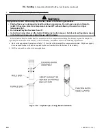
Page 53: ...nstallation of Duravent PolyPro UV Resistant Single Wall Horizontal Terminal Figure 7 37 Installation of Duravent PolyPro UV Resistant Single Wall Vertical Terminal VII Venting F Assembly of DuraVent...

Page 54: ...e Seal the termination to the exterior wall plate with weather resistant RTV f Slide the interior wall plate over the termination and attach to the wall from inside the room g Attach the interior wal...

Page 55: ...7 39 Installation of Duravent PolyPro Concentric Vent Terminal Through Sidewall VII Venting F Assembly of DuraVent PolyPro Vent Systems continued Figure 7 40 Installation of Duravent PolyPro Concentr...

Page 56: ...p using a 2 or 3 electrical conduit lock nut Seal all joints with RTV G Assembly of Selkirk Polyflue Vent Systems WARNING Asphyxiation Hazard When using PolyPro flex observe the following precautions...

Page 57: ...exhaust coupling and insert Selkirk 2PF HVST or 3PFHVST in its place c A 180 bend or two 90 elbows are installed on the top of the air intake pipe If two 90 elbows are used a rodent screen can be inst...

Page 58: ...ference the Selkirk Polyflue instruction manual Not all vent configurations shown in the Selkirk vent manual are listed for use with this boiler Refer to Selkirk Polyflue Instructions for assembly of...

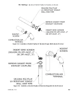
Page 59: ...Assembly of Selkirk Polyflue Vent Systems continued Figure 7 42 Installation of Selkirk Polyflue UV Resistant Single Wall Horizontal Terminal Figure 7 43 Installation of Selkirk Polyflue UV Resistant...

Page 60: ...re 7 27 A locking band clamp in the adaptor prevents the vent pipe from coming out of the adaptor once it is installed and tightened Lubricate the gaskets in the vent adaptor with water and insert the...

Page 61: ...venting component manufacturer Centrotherm Polypropylene pipe sections must be disengaged 1 4 in 6mm per joint to allow for thermal expansion 4 Installation of Horizontal Fitting Terminals Terminal Op...

Page 62: ...tallation of Centrotherm InnoFlue UV Stabilized Single Wall Horizontal Terminal Figure 7 46 Installation of Centrotherm InnoFlue UV Stabilized Single Wall Vertical Terminal VII Venting H Assembly of C...

Page 63: ...Tables 7 13b or 7 21 for a list of the principle flex components required Rigid vent pipe by the same manufacturer will also be required for the run from the boiler to the base of chimney b Masonry c...

Page 64: ...iping may be PVC c There is a 0 minimum clearance between the air intake piping and all types of construction d To the extent possible pitch horizontal air intake piping towards the outside WARNING As...

Page 65: ...ible stainless steel pipe manufacturer installation instructions and Boiler Installation Operating and Service Instructions the more restrictive instructions shall govern WARNING Asphyxiation Hazard F...

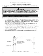
Page 66: ...nd of the extension as shown in Figure 7 47 2 Condensate is slightly acidic Do not use metallic pipe or fittings in the condensate drain line Do not route the drain line through areas that could be da...

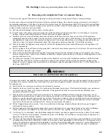
Page 67: ...e ANSI Z223 1 VII Venting K Removing an Existing Boiler From a Common Chimney WARNING Never common vent this boiler with other appliances Au moment du retrait d une chaudi re existante les mesures sui...

Page 68: ...rom the gas supply system by closing its individual manual shut off valve Locate leaks using an appropriate combustible gas non corrosive leak detector solution VIII Gas Piping WARNING Explosion Hazar...

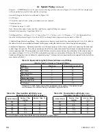
Page 69: ...on fitting located on the bottom of the boiler If an additional regulator is used to reduce boiler inlet pressure below 1 2 psig 3 4 kPa it must be at least 6 to 10 ft upstream of the boiler It is ver...

Page 70: ...important guideline Tap water contains dissolved oxygen which causes corrosion In a tight system this oxygen comes out of solution and is quickly removed from the system through the automatic air vent...

Page 71: ...water 6 AutomaticAirVent required Atleastoneautomaticairventisrequired Manualairventswillusuallyberequired in other parts of the system to remove air during initial fill 7 Manual Reset High Limit requ...

Page 72: ...ly effective way to provide such protection Section HG614 c of the 2013 ASME boiler and Pressure Vessel Code recognizes the use of a listed flow switch in lieu of a low water cut off on water tube boi...

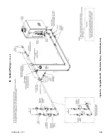
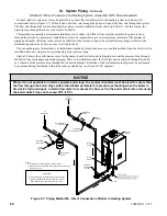
Page 73: ...ping between the expansion tank and secondary connection tees must be at least 1 In order to keep the flow rates in the system and boiler loops independent of each other provide at least 8 diameters o...

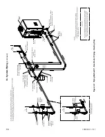
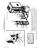
Page 74: ...Air Vent Header Temperature Sensor When Used Y Strainer Recommended To System System Zone Valves Heating System Circulator Boiler Pump Drain Valve Full Port Isolation Valves Unions Tee Plug Recommende...

Page 75: ...ze the load placed on the Primary Secondary Header connections 3 Components marked are supplied with the boiler All other components are supplied by the installer 4 3 4 coupling and 3 4 x 4 nipple mar...

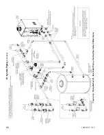
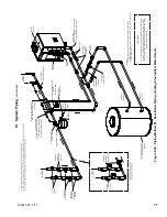
Page 76: ...76 107672 01 7 17 Figure 9 3a Piping Method 1 Near Boiler Piping Heating Plus Indirect Water Heater IX System Piping continued...

Page 77: ...Port Isolation Valves Tee Plug Recommended For Future Heat Exchanger Service Relief Valve Close Nipple Locate Header Sensor As Close As Possible To Downstream Tee Hydraulic Separator May Be Substitut...

Page 78: ...lso generally provide effective connection points for automatic air elimination devices and an expansion tank These separators are available from several sources and may be used in place of the closel...

Page 79: ...79 107672 01 7 17 Figure 9 6 Piping Method 1 Near Boiler Piping Shaded Boiler Loop IX System Piping continued...

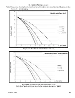
Page 80: ...e curve for the pump in each boiler model taking into account the pressure drop through the boiler s heat exchanger and internal piping These curves therefore show the flow that can be achieved throug...

Page 81: ...st use Speed HI to achieve the flow requirement shown in Table 9 1 Figure 9 8a Taco Net Circulator Performance Curve Note These curves show the flow that can be achieved through the boiler as a functi...

Page 82: ...ne additions of fresh water Systems which are open to the atmosphere If the boiler is to be used in such a system it must be separated from the oxygenated water being heated with a heat exchanger as s...

Page 83: ...83 107672 01 7 17 PAGE LEFT INTENTIONALLY BLANK...

Page 84: ...dlock once power is turned off WARNING All wiring and grounding must be done in accordance with the authority having jurisdiction or in the absence of such requirements with the National Electrical Co...

Page 85: ...ction XII of this manual for information on setting up the pump operation 2 Low Voltage Connections Low voltage field connections on the low voltage PCB are shown in Figure 10 3 and are listed from to...

Page 86: ...86 107672 01 7 17 Figure 10 2 High Voltage PCB Terminal Connections Figure 10 3 Low Voltage PCB Terminal Connections X Wiring continued...

Page 87: ...h as transformers power lines and fluorescent lighting Wire the sensor to the boiler using 22 gauge or larger wire As with the sensor itself the sensor wiring should be routed away from sources of ele...

Page 88: ...imary Secondary Tee Sensor Clip Header Temperature Sensor Honeywell 32003971 003 U S B C P N 103104 01 Close Nipple Locate Header Sensor As Close As Possible To Downstream Tee Well Should Extend Into...

Page 89: ...89 107672 01 7 17 X Wiring continued Figure 10 5 Internal Ladder Diagram...

Page 90: ...90 107672 01 7 17 X Wiring continued...

Page 91: ...91 107672 01 7 17 Figure 10 6 Internal Wiring Connections Diagram X Wiring continued...

Page 92: ...2 STRIP 40b BL SPL BL 1 J8 1 15 GR J4 12 GND 41 YE P8 4 J8 3 16 OR IGNITOR 42 YE P8 5 J7 7 17 P G P10 1 J10 7 43 GY P8 12 SPL GY 1 18 YE P10 2 J10 8 43a GY SPY GY 1 THERM 1 19 P G P10 3 J8 11 43b GY...

Page 93: ...93 107672 01 7 17 Figure 10 8 TACO SR504 or Equivalent Zone Panel Wiring Connection Diagram X Wiring continued...

Page 94: ...94 107672 01 7 17 X Wiring continued Figure 10 9 Sage Zone Control Circulator Panel Wiring Connection Diagram...

Page 95: ...ve hose 7 Check all gas piping for leaks and purge piping sections that are filled with air Refer to the National Fuel Gas Code for additional information on testing and purging gas lines 8 Confirm ve...

Page 96: ...are a blend of glycol for freeze protection and inhibitors to protect the glycol from attacking metallic system components Do not add any more antifreeze than is necessary to protect the system from f...

Page 97: ...ignition or if the boiler fails to light after six tries for ignition the blinking HELP button is highlighted on the Home screen Figure 11 2c Touching this HELP button will take the user to the Diagno...

Page 98: ...72 01 7 17 Figure 11 3 Burner Flame XI Start Up and Checkout continued Figure 11 2a Home Screen at Power Up No Call for Heat Figure 11 2b Home Screen on Heat Demand Figure 11 2c Home Screen with Activ...

Page 99: ...ing Figure 11 4 Gas Valve Detail 80MBH thru 180MBH WARNING Do not attempt to operate this boiler on LP gas without converting it using the proper conversion kit Do not attempt to convert this boiler t...

Page 100: ...ts of 1 8 and 1 4 turns and allow the boiler at least a minute to respond to each adjustment With the burner at low fire adjust offset regulator as needed to obtain CO2 or O2 setting shown in Table 11...

Page 101: ...O Air Free Range Target 080 8 7 9 2 9 1 200ppm 100 120 150 180 Low Fire Range and Target values are the same as High Fire above Ensure low fire CO2 reading is less than or equal to high fire CO2 readi...

Page 102: ...102 107672 01 7 17 Lighting and Operating Instructions XI Start Up and Checkout continued...

Page 103: ...is boiler is not used for any space heating This boiler is part of a modular or multiple boiler system having a total input of 300 000 BTU hr or greater This boiler is equipped with a combi space heat...

Page 104: ...accepts a call for heat demand from multiple places and responds according to it s Priority When more than 1 demand is present the higher priority demand is used to determine active boiler settings Fo...

Page 105: ...is cycled off XII Operation continued If the temperature exceeds 210 F 98 9 C a manual reset hard lockout results If the boiler is responding to theinternalMultipleBoilerControlSequencer Header Sensor...

Page 106: ...encer Master enabled Control 3 Lead SlaveSequencing EqualizedRunTime One boiler is a Lead boiler and the remaining networked boilers are Slaves When demand is increasing the Lead boiler is the first t...

Page 107: ...ciency by helping increase the amount of flue gas water vapor condensation The Control maintains a Base Load Common Rate until the last lag boiler is started At this point the Base Load Common Rate is...

Page 108: ...Running burner On circulator s On After flame is proven the sequence continues with run stabilization and low fire hold time Once the field adjustable low fire hold time is completed normal boiler ope...

Page 109: ...at Domestic Hot Water Sequencer Control peer to peer Demand or Frost Protection Warm Weather Shutdown status is shown Standby is shown when no demand is present Energy Save On Indication Outdoor Air R...

Page 110: ...bol These screens are accessed by selected the Status button from the Home screen Figure 12 6 Status Screens Figure 12 7 Boiler Status Screen Definitions NOTE Only visible if Zone Panel is connected Z...

Page 111: ...reen provides the status of the boiler s demand to connected pumps as well as the status of Frost Protection and pump Exercise functions This screen provides the status of the boilers five 5 possible...

Page 112: ...l Screens Figure 12 8 Detail Screen Overview Zone Control Status press for zone cycles i Zone Panel 1 Demand Cycles KITCHEN 45 BEDROOMS 20 BASEMENT 12 DOMESTIC HOT WATER 26 Active zones are shown by b...

Page 113: ...e Of Operation continued 5 Multiple Boiler Sequencer Screens When the Sequence Master is enabled the following screen is available The Sequencer Status screen is selected by pressing Status button fro...

Page 114: ...and press the return arrow to close the keypad Press the Save button Press the Adjust button to enter Adjustment mode Figure 12 9 Adjust Mode Screens Login to Access Adjustment Mode For Service Contac...

Page 115: ...nsor is not connected to the boiler the sensor is not monitored for faults Wired Outdoor Sensor is installed directly on the boiler terminal Strip Wireless Outdoor sensor is installed and wireless Ena...

Page 116: ...lation rate the Control will go to during a Domestic Hot Water call for heat If the rated input of the indirect water heater is less than the maximum output of the boiler change the DHW Maximum Expect...

Page 117: ...M 8100 8500 8000 Minimum Heat rate RPM 1710 1800 1500 Default Light off RPM 4000 4000 4000 Altitude 6001 7800 FT Model K2WT 080B 67 K2WT 100B 67 N K2WT 120B 67 N K2WT 150B 67 K2WT 180B 67 N Maximum He...

Page 118: ...he maximum heat rate the Control then measures water temperature and fires the boiler only as hard as required for the heat demand Expected Heat Rate Adjustment Screens HeatMatch Software Example call...

Page 119: ...emand Never Any Demand Header Sensor Demand CH Off for DHW Boiler Pump run pump for Activates the boiler pump output according to selected function Never Pump is disabled and not shown on status scree...

Page 120: ...n This piping arrangement permits the system pump to run or not run when there is a domestic hot water call for heat Domestic hot water priority is optional It is permissible for the domestic and syst...

Page 121: ...lators Optional Full Port Isolation Valves Optional Full Port Isolation Valves To System From System Air Separator Air Vent Expansion Tank Header Temperature Sensor When Used Cold Water Line Y Straine...

Page 122: ...c hot water call for heat Domestic hot water priority is optional It is permissible for the domestic and system pumps to run at the same time The boiler pump must run for every call for heat Example P...

Page 123: ...Description Contractor Name User defined Contractor Name Address Line 1 User defined Contractor Address Line 1 Address Line 2 User defined Contractor Address Line 2 Phone User defined Contractor Phone...

Page 124: ...ure controller Proportion Integral Derivative PID values Higher values cause a larger firing rate change for each degree of temperature change If set too high firing rate overshoots required value inc...

Page 125: ...g the temperature to exceed the Diff Above setpoint and cycle the boiler unnecessarily Lower values cause a smaller firing rate change for each degree of temperature change If set too low the firing r...

Page 126: ...xceed the Diff Above setpoint and cycle the boiler unnecessarily Lower values cause a smaller firing rate change for each degree of temperature change If set too low the firing rate response will be s...

Page 127: ...F 21 1 C 32 F to 100 F 0 C to 37 8 C Central Heat High Outdoor Temperature The High Outdoor Temperature parameter is the outdoor temperature at which the Low Boiler Water Temperature is supplied This...

Page 128: ...100 F 40 C to 37 8 C Auxiliary Heat Low Outdoor Temperature The Low Outdoor Temperature parameter is also called Outdoor Design Temperature This parameter is the outdoor temperature used in the heat...

Page 129: ...Setpoint Heating Element Type 180 F to 190 F 82 2 C to 87 8 C Fan Coil 100 F to 140 F 37 8 C to 60 C In Slab Radiant High Mass Radiant 160 F to 190 F 71 1 C to 87 8 C Convection Baseboard Fin Tube Con...

Page 130: ...ond to rapid load increases 70 50 100 Base Load Common Rate To maximize condensing boiler efficiency the firing rate is limited to an adjustable value Boilers are kept at or below this firing rate as...

Page 131: ...nd J10 8 is used as the temperature setpoint The following two parameters may be used to adjust the signal range Modbus Modbus is used as the temperature setpoint 130 F 54 4 C 80 F 26 7 C Central Heat...

Page 132: ...approved respirator 2 Long sleeved loose fitting clothing 3 Gloves 4 Eye Protection Take steps to assure adequate ventilation Wash all exposed body areas gently with soap and water after contact Wash...

Page 133: ...y metals carbon monoxide nitrogen oxides aldehydes and or other toxic or harmful substances which can cause death or serious injury and which are known to the state of California to cause cancer birth...

Page 134: ...erify that the gas shutoff shown in Figure 8 1 is closed e Disconnect the flexible gas line at the gas valve flare connection Figure 13 1 f Unplug the electrical connection to the gas valve g Disconne...

Page 135: ...Gas Line Figure 13 2 Flame Ionization Electrode and Ignition Electrode Location XIII Service and Maintenance continued When disconnecting exible gas line Place a backup wrench on this nut to prevent...

Page 136: ...on the bottom of the boiler see Figure 2 1 to catch water in the trap as well as the ball and ball support Unscrew the cap being careful not to lose the ball or ball support Flush any debris found in...

Page 137: ...137 107672 01 7 17 XIII Service and Maintenance continued Figure 13 3 Ignition Electrode Gap Figure 13 4 Condensate Trap Exploded Parts View...

Page 138: ...r water and the use of boiler water additives NOTICE Do not remove return pipe connection from heat exchanger to service the circulator u Test the flow switch To do this Start with the boiler in stand...

Page 139: ...Help button flashes and the home screen turns a red color Continue to select flashing buttons to be directed to the Fault cause B Display Faults Indication Condition Possible Cause Display Completely...

Page 140: ...then Disabled Master s Boiler has been powered down To clear fault restore communication or cycle power Boiler Size Setup Boiler Size Fault WARNING Boiler size setting may not match actual boiler siz...

Page 141: ...owing messages appear when the firing rate is limited or reduced to help avoid a lockout or save energy Refer to Hard Lockout section for corrective actions High Stack Temperature Limit High Supply Te...

Page 142: ...witch Special Note Before a call for heat the air pressure switch is closed When there is a call for heat with a blocked vent the air pressure switch will open due to excessive pressure of the blower...

Page 143: ...for blower speed to match purge and light off setpoint Normal waiting for blower speed to match purge and light off setpoint 27 Undefined Fault Undefined Fault Consult Factory 28 or 53 Air Proving Swi...

Page 144: ...ed or dirty drain line in trap 18 Light off rate proving failed Blower is not running at Light off rate when it should or blower speed signal not being detected by Control Loose connection in 120 VAC...

Page 145: ...your local U S Boiler Wholesale distributor Should you require assistance in locating a U S Boiler distributor in your area or have questions regarding the availability of U S Boiler products or serv...

Page 146: ...5879 01 11A 11B 11C Flame Rod includes flame rod gasket and hardware 105880 01 12A 12B 12C Ignition Electrode includes electrode gasket and hardware 105881 01 13 M6 Serrated Flange Hex Burner Door Nut...

Page 147: ...147 107672 01 7 17 XV Service Parts continued...

Page 148: ...871 01 Not Shown LP Gas Conversion Kit excludes M models 107873 01 107874 01 107875 01 27 28 29 Blower Outlet Gasket 106029 01 30 31 34 CSST Gas Line Assembly includes gas line assembly and gasket 106...

Page 149: ...0 100 120 150 180 51 52 53 Condensate Trap includes gasket bracket and trap ball 105851 01 54 55 56 57 59 Silicone Tubing includes 3 16 and 3 4 tubing spring clamp and vent fitting 105855 01 58 Sump P...

Page 150: ...50 180 67 68 69 73 Low Voltage Printed Circuit Board PCB includes Low Voltage PCB and hardware 105853 01 67 70 71 72 73 High Voltage Printed Circuit Board PCB includes Line Voltage PCB insulator gaske...

Page 151: ...151 107672 01 7 17 XV Service Parts continued...

Page 152: ...Number Qty 080 100 120 150 180 75 Transformer 106034 01 76 Sage 2 3 Boiler Control 107877 01 77 78 82 97 Control Door Parts 107872 01 79 8 18 x 1 2 Self Tapping Screw Obtain locally 80 Programmable Di...

Page 153: ...153 107672 01 7 17 XV Service Parts continued 85 86 91 95...

Page 154: ...PVC Intake Coupling with Locknut 105848 01 95 Vent Connector includes connector gasket and hardware 107034 01 96 8 18 x 1 2 Screw Obtain locally 98 1 8 x 1 x 3 Hinge Pin Obtain locally 103 105 Jacket...

Page 155: ...NPT x 2 Nipple Obtain locally 119 1 NPT Tee with Side Outlet 107895 01 120 1 x 1 4 NPT Hex Reducing Bushing Obtain locally 121 Temperature Pressure Gauge 105894 01 122 1 x 3 4 NPT Hex Reducing Bushin...

Page 156: ...er 080 100 120 150 180 130 Low Voltage Communication 107876 01 131 High Voltage Harness 105868 01 132 133 135 Trap Flame Trap Ground Circulator Pigtail includes wire harness 105870 01 134 Ignition Cab...

Page 157: ...s injury and or reduced component life Adjusting Boiler Type must be completed first Select the correct K2WT boiler size altitude and fuel range using the touch screen display as follows 1 Check boile...

Page 158: ...9 8 9 8 Low Fire Range and Target values are the same as High Fire above Ensure low fire CO2 reading is less than or equal to high fire CO2 reading Model No Fuel Measured O2 Max Co Air Free 2001 6000...

Page 159: ...proximate Derate per 1000 ft 2001 6000 ft 6001 7800 ft 7801 10 100 ft K2WT 080B NG 0 9 4 0 4 0 LP Not Permitted K2WT 100B NG 1 9 2 6 2 7 LP 3 1 3 8 4 0 K2WT 120B NG 1 2 1 8 2 4 LP 1 7 3 3 Not Permitte...

Page 160: ...period of thirty 30 days to comply with the above requirements provided however that during said thirty 30 day period a battery operated carbon monoxide detector with an alarm shall be installed 2 AP...

Page 161: ...rements shall be satisfied by the manufacturer 1 The referenced special venting system instructions shall be included with the appliance or equipment installation instructions and 2 The special ventin...

Page 162: ...162 107672 01 7 17...

Page 163: ...163 107672 01 7 17...

Page 164: ...164 107672 01 7 17...

Page 165: ...165 107672 01 7 17...

Page 166: ...166 107672 01 7 17...

Page 167: ...167 107672 01 7 17...

Page 168: ...168 107672 01 7 17 U S Boiler Company Inc P O Box 3020 Lancaster PA 17604 1 888 432 8887 www usboiler net...

Reviews: