
37
107672-01- 7/17
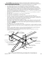
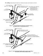
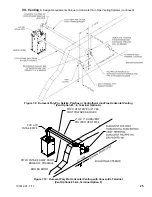
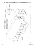
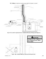
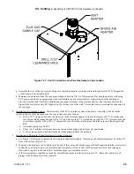
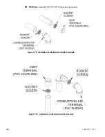
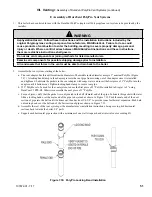
VII. Venting
D. Design Requirements Unique to Split Vent Systems (continued)
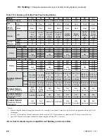
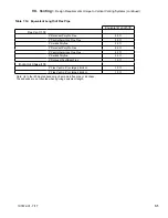
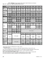
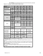
Table 7.21: Summary of Split Vent System Options (cont.)
Option #
25
26
27
28
29
30
Illustrated in Figure
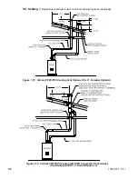
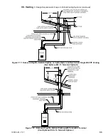
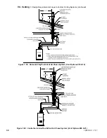
7.22
7.22
7.22
7.22
7.22
7.22
Pipe Penetration
Through Structure
Vent
Roof
Roof
Roof
Roof
Roof
Roof
Intake
Wall
Wall
Wall
Wall
Wall
Wall
Material
Vent
CPVC/PVC
(Note 2)
CPVC/PVC
(Note 2)
DuraVent
PolyPro
(Ridgid)
DuraVent
PolyPro
(Ridgid)
Selkirk
Polyflue
Selkirk
Polyflue
Intake
PVC
PVC
PVC
PVC
PVC
PVC
Nominal Diameter
Vent
2”
3”
2”
3”
2”
3”
Intake
2” or 3”
3”
2” or 3”
3”
2” or 3”
3”
Min Equivalent Vent Length:
Models
080
48”
48”
48”
48”
48”
48”
100
48”
48”
48”
48”
48”
48”
120
Not Permitted
48”
Not Permitted
48”
Not Permitted
48”
150
52”
52”
52”
180
52”
52”
52”
Max Equivalent Vent Length (Note 1):
Models
080
60ft
135ft
60ft
135ft
60ft
135ft
100
60ft
135ft
60ft
135ft
60ft
135ft
120
Not Permitted
135ft
Not Permitted
135ft
Not Permitted
135ft
150
135ft
135ft
135ft
180
135ft
135ft
135ft
Rigid Vent
Terminals
Vent
Coupling w
Screen
Coupling w
Screen
2PPS-12B or
2PPS-36B w
Screen
3PPS-12B or
3PPS-36B w
Screen
2PF-10UV or
2PF-39UV w
Screen
3PF-10UV or
3PF-39UV w
Screen
Intake 90 Elbow w
Screen
90 Elbow w
Screen
90 Elbow w
Screen
90 Elbow w
Screen
90 Elbow w
Screen
90 Elbow w
Screen
Flex Termination
& Components
(Masonry Chimney
Chase) (Note 3)
Vent
Not Permitted
Intake
Flex Termination
& Components
(B-Vent Chimney
Chase)
Vent
Not Permitted
Intake
* Specify size of B vent (e.g. 2PPS-BV
6
is for use with 6” B vent)
** Specify length in feet.
**** Specify Flex length and B vent diameter (e.g. IFBK02
2505
includes 25ft of flex and used with 5” B vent)
Note 1: Max vent lengths shown also apply to the intake. Flex vent reduces the maximum allowable vent length in some cases
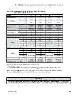
See equivalent lengths for flex vent shown in Table 7.14 and sizing example on page 35.
Note 2: First 30” plus first exhaust elbow are CPVC.
Note 3: See Vent Manufacturer’s installation manual for gaskets, spacers and other required vent components.
All vertical terminals require compatible roof flashing and storm collars
.
Summary of Contents for K2WT-080B
Page 83: ...83 107672 01 7 17 PAGE LEFT INTENTIONALLY BLANK...
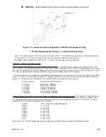
Page 89: ...89 107672 01 7 17 X Wiring continued Figure 10 5 Internal Ladder Diagram...
Page 90: ...90 107672 01 7 17 X Wiring continued...
Page 91: ...91 107672 01 7 17 Figure 10 6 Internal Wiring Connections Diagram X Wiring continued...
Page 102: ...102 107672 01 7 17 Lighting and Operating Instructions XI Start Up and Checkout continued...
Page 147: ...147 107672 01 7 17 XV Service Parts continued...
Page 151: ...151 107672 01 7 17 XV Service Parts continued...
Page 153: ...153 107672 01 7 17 XV Service Parts continued 85 86 91 95...
Page 162: ...162 107672 01 7 17...
Page 163: ...163 107672 01 7 17...
Page 164: ...164 107672 01 7 17...
Page 165: ...165 107672 01 7 17...
Page 166: ...166 107672 01 7 17...
Page 167: ...167 107672 01 7 17...


