


14
107672-01 - 7/17
VII. Venting
A. Vent System Design
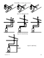
There are three basic ways to vent this boiler:
•
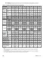
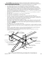
Horizontal (“Side Wall”) Twin Pipe Venting (Figure 7.0a)
- Vent system exits the building through an outside wall.
Combustion air and flue gas are routed between the boiler and the terminal(s) using separate pipes for at least part of the
way. A summary of Horizontal Twin Pipe venting options is shown in Table 7.5.
•
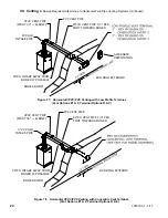
Vertical Twin Pipe Venting (Figure 7.0b)
- Vent system exits the building through a roof. Combustion air and flue gas
are routed between the boiler and the terminal(s) using separate pipes for at least part of the way. A summary of Vertical
Twin Pipe venting options is shown in Table 7.13
•
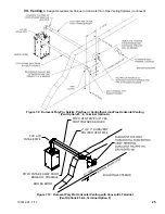
Split Venting (Figure 7.0c)
- Exhaust system exits the building through a roof, and combustion air is drawn from a
terminal mounted on the side wall. A summary of split venting options is shown in Table 7.21
All of these systems are considered “direct vent” because the air for combustion is drawn directly from the outdoors into the
boiler. One of the vent option columns in Tables 7.5, 7.13, 7.21 must match the planned vent and air intake system exactly.
Design details applying to all vent systems are shown in this section. Observe all design requirements in this section, as well as
those unique to the type of system being installed:
• B - Design Requirements Unique to Horizontal Twin Pipe Vent Systems
• C - Design Requirements Unique to Vertical Twin Pipe Vent Systems
• D - Design Requirements Unique to Split Vent Systems
1. Listed Vent Systems and Materials – The following materials and vent systems may be used to vent this boiler:
• CPVC – Use only CPVC listed to ASTM F441. In Canada, this pipe must also be listed to ULC S636.
• PVC – PVC may be used only as permitted in this manual. All PVC must be listed to ASTM D2665. At least 30” of CPVC
pipe, and at least one CPVC elbow, must be installed between the boiler’s vent connection and the PVC pipe. Use of
foam core PVC is not permitted for venting. PVC vent pipe may not be used to vent this boiler in Canada.
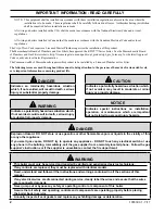
Warning
Asphyxiation Hazard. Failure to vent this boiler in accordance with these instructions could cause
products of combustion to enter the building resulting in severe property damage, personal injury or
death.
Do not interchange vent systems or materials unless otherwise specified.
The use of thermal insulation covering vent pipe and fittings is prohibited.
Do not use a barometric damper, draft hood or vent damper with this boiler.
When using the CPVC/PVC vent option, the use of CPVC is required when venting in vertical or
horizontal chase ways.
Any CPVC vent materials supplied with this boiler do not comply with B149.1.S1-07 and are not
approved for use in Canadian jurisdictions that require vent systems be listed to ULC S636-2008. In
these jurisdictions, vent this boiler using a listed ULC S636 Class IIB venting system.
Do not locate vent termination where exposed to prevailing winds. Moisture and ice may form on
surface around vent termination. To prevent deterioration, surface must be in good repair (sealed,
painted, etc.).
Do not locate air intake vent termination where chlorines, chlorofluorocarbons (CFC’s), petroleum
distillates, detergents, volatile vapors or other chemicals are present. Severe boiler corrosion and
failure will result.
The use of cellular core PVC (ASTM F891), cellular core CPVC or Radel (polyphenolsulfone) is
prohibited.
Do not locate vent termination under a deck.
Do not reduce specified diameters of vent and combustion air piping.
When installing vent pipe through chimney, as a chase, no other appliance can be vented into the
chimney.
Do not allow low spots in the vent where condensate may pool.
Summary of Contents for K2WT-080B
Page 83: ...83 107672 01 7 17 PAGE LEFT INTENTIONALLY BLANK...
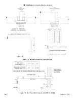
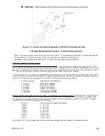
Page 89: ...89 107672 01 7 17 X Wiring continued Figure 10 5 Internal Ladder Diagram...
Page 90: ...90 107672 01 7 17 X Wiring continued...
Page 91: ...91 107672 01 7 17 Figure 10 6 Internal Wiring Connections Diagram X Wiring continued...
Page 102: ...102 107672 01 7 17 Lighting and Operating Instructions XI Start Up and Checkout continued...
Page 147: ...147 107672 01 7 17 XV Service Parts continued...
Page 151: ...151 107672 01 7 17 XV Service Parts continued...
Page 153: ...153 107672 01 7 17 XV Service Parts continued 85 86 91 95...
Page 162: ...162 107672 01 7 17...
Page 163: ...163 107672 01 7 17...
Page 164: ...164 107672 01 7 17...
Page 165: ...165 107672 01 7 17...
Page 166: ...166 107672 01 7 17...
Page 167: ...167 107672 01 7 17...


