background image

USER GUIDE

Ice 1

u-line.com

SAFETY • INSTALLATION & INTEGRATION • 

OPERATING INSTRUCTIONS 

• MAINTENANCE • SERVICE

Ice

ICE MAKER OPERATION

When the ice bucket is full, the ice making mechanism will 
shut off. However, the refrigeration system will continue 
to cool and maintain the ice supply.

NOTICE

Do not place cans or bottles in the ice 
compartment because they will freeze.

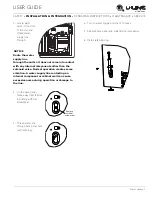
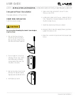
To turn off ice production:

 Raise the bin arm into 

an upright and locked position. The unit will preserve 
temperature for ice storage. 

NOTICE

If not intending to use the ice maker, turn the 
water supply valve off. It is also important to 
raise the bin arm of the ice maker (see above). 
Failure to raise the bin arm may result in damage 
to the water valve.

Certain sounds are normal during the unit’s operation. You 
may hear the compressor or fan motor, the water valve, 
or ice dropping into the ice bucket.

CAUTION

!

NEVER use an ice pick, knife or other sharp 
instrument to separate cubes. Shake the ice 
bucket instead.

During periods of limited use or high ambient 
temperatures, it is common for cubes to fuse together. 
Gently shake the bucket to break apart cubes. If not using 
the ice maker regularly, empty the ice bucket periodically 
to ensure fresh cubes.

It is normal for cubes to appear cloudy. The cause is air 
trapped in the water because of fast freezing. It is not 
caused by the health, taste or chemical make up of the 
water. It is the same air that is in every glass of water you 
drink.

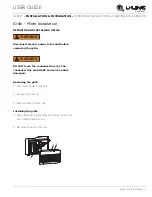
Remove the ice bucket for emptying and cleaning. To 
remove the ice bucket, raise the bin arm and remove the 
bucket from the ice compartment. Use the ice bucket for 
ice storage only.

OFF

ON

Summary of Contents for Origins BI-98

Page 1: ...USER GUIDE SAFETY INSTALLATION INTEGRATION OPERATING INSTRUCTIONS MAINTENANCE SERVICE ADA Height Compliant Series BI98 15 Crescent Ice Maker RIGHT PRODUCT RIGHT PLACE RIGHT TEMPERATURE SINCE 1962...

Page 2: ...l Requirements Electrical Cutout Dimensions Product Dimensions Water Hookup General Installation Integrated Panel Dimensions Integrated Panel Installation Grille Plinth Installation Door Swing Door Ad...

Page 3: ...ship to you PRODUCT INFORMATION Looking for additional information on your product User Guides Quick Reference Guides CAD Drawings Compliance Documentation and Product Warranty information are all ava...

Page 4: ...sted throughout this guide SAFETY ALERT DEFINITIONS Throughout this guide are safety items labeled with a Danger Warning or Caution based on the risk type DANGER Danger means that failure to follow th...

Page 5: ...freezer take off the doors and leave shelves in place so children may not easily climb inside If the unit is being removed from service for disposal check and obey all federal state and local regulati...

Page 6: ...C or higher may reduce the unit s ability to reach low temperatures For best performance keep the unit out of direct sunlight and away from heat generating equipment In climates where high humidity a...

Page 7: ...use an extension cord to connect power to the unit Always keep your working area dry NOTICE Electrical installation must observe all state and local codes This unit requires connection to a grounded...

Page 8: ...e is required for an electrical and water connection in the rear NOTICE Units can NOT be installed behind a closed cabinet door CUT OUT DIMENSIONS NOTICE It is extremely important that this unit sits...

Page 9: ...uct Dimensions 1 u line com SAFETY INSTALLATION INTEGRATION OPERATING INSTRUCTIONS MAINTENANCE SERVICE Product Dimensions 27 3 8 695 mm 14 15 16 379 mm 20 508 mm Add 1 1 2 For For Water Line Clearance...

Page 10: ...pply line The water line should be looped into 2 coils This will allow the unit to be removed for cleaning and servicing Make certain that the tubing is not pinched or damaged during installation WARN...

Page 11: ...components other than the solenoid valve Normal operation creates some vibration A water supply line contacting an internal component or cabinet wall can cause excessive noise during operation or dama...

Page 12: ...not level the ice mold will not fill evenly Use a level to confirm the unit is level Level should be placed along top edge and side edge as shown INSTALLATION 1 Plug in the power electrical cord 2 Ge...

Page 13: ...door panels can be flat or raised as long as the maximum panel thickness where inserted into the door reveal channel is no more than 1 4 6 mm thick For raised panels the depth of the reveal is 1 4 6 m...

Page 14: ...Pull door gasket out of groove top edge of door only Start in the middle and pull outward moving toward the edge This may take some force 3 Remove top screw on each side securing door handle Slightly...

Page 15: ...nnect electric power to the unit before removing the grille WARNING DO NOT touch the condenser fins 4 The condenser fins are SHARP and can be easily damaged Removing the grille 1 Disconnect power to t...

Page 16: ...TION OPERATING INSTRUCTIONS MAINTENANCE SERVICE Door Swing All units have a zero clearance for the door to open 90 U Line recommends a minimum door clearance of 1 4 6 mm to accommodate the handle if t...

Page 17: ...of the door ALIGNMENT AND ADJUSTMENT 1 Loosen do not remove top and bottom hinge screws 2 Align door squarely with cabinet Make sure gasket is firmly in contact with cabinet all the way around the do...

Page 18: ...on the opposite side of the door Do not place handle on door until you have completed step 9 9 Remove plastic hole plug from door handle and relocate to opposite side Lift the handle slightly and pre...

Page 19: ...assembly 13 Place the door latch assembly on opposite side of unit Be sure to tighten all three screws securely 14 Place door on lower hinge pin Invert and install upper hinge on door Fasten upper hin...

Page 20: ...at the factory Initial startup requires no adjustments NOTICE U Line recommends discarding the ice produced during the first two to three hours of operation to avoid possible dirt or scale that may d...

Page 21: ...rtain sounds are normal during the unit s operation You may hear the compressor or fan motor the water valve or ice dropping into the ice bucket CAUTION NEVER use an ice pick knife or other sharp inst...

Page 22: ...igns on the control box CAUTION Too large of an adjustment to the screw can cause the water to overflow the ice maker and can cause property damage 3 Turn the adjusting screw toward the minus sign clo...

Page 23: ...GRATION OPERATING INSTRUCTIONS MAINTENANCE SERVICE Airflow and Product Loading NOTICE The unit requires proper airflow to perform at its highest efficiency Do not block the front grille at any time or...

Page 24: ...eaners or polishes on any glass surfaces Clean any glass surfaces with a non chlorine glass cleaner Do not use cleaners not specifically intended for stainless steel on stainless surfaces this include...

Page 25: ...ower to the unit 2 Remove ice bucket and discard ice 3 Place towel or other absorbent material on bottom of ice bin 4 Fill the ice bucket half full with warm not hot water This will help the unit defr...

Page 26: ...ntal conditions more or less frequent cleaning may be necessary WARNING Disconnect electric power to the unit before cleaning the condenser WARNING DO NOT touch the condenser fins The condenser fins a...

Page 27: ...ter is removed from the lines 7 The door must remain open to prevent formation of mold and mildew Open door a minimum of 2 50 mm to provide the necessary ventilation WINTERIZATION If the unit will be...

Page 28: ...1 u line com SAFETY INSTALLATION INTEGRATION OPERATING INSTRUCTIONS MAINTENANCE SERVICE Accessories 80 51004 00 Accessories Anti Tip Mounting Brackets US 18 99 WATERHOOKUP Accessories Braided Water Li...

Page 29: ...dency to reflect normal appliance operating noises Listed below are common refrigeration components with a brief description of the normal operating sounds they make NOTE Your product may not contain...

Page 30: ...erature setting Ambient temperature where installed Installation in direct sunlight or near a heat source The number of door openings and the time the door is open The time the internal light is illum...

Page 31: ...ervice com 3 The warranty listed above does not apply to floor display models The warranty for these models shall be 30 days from the date of retail purchase and only if U Line s Product Registration...

Page 32: ...IS IN LIEU OF ANY AND ALL OTHER WARRANTIES EXPRESS OR IMPLIED INCLUDING ANY IMPLIED WARRANTY OF MERCHANTABILITY OR IMPLIED WARRANTY OF FITNESS FOR A PARTICULAR PURPOSE ALL OF WHICH ARE DISCLAIMED U Li...

Reviews: