background image

-22-

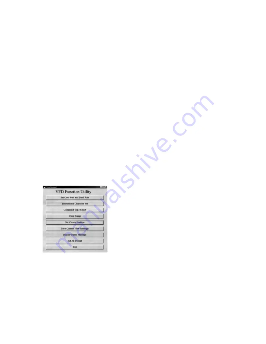
5. Then, follow this menu to run the demo software.

a. Click "Set COM Port and Baud Rate", to set

RS-232 communication of the computer. Select

COM port, baud rate must also be set as the

same as the baud rate shown on the lower line

of the display, such as "9600 N 8 1" means

baud rate 9600, no parity, 8 data bits, and 1

stop bit.

b. Click "International Character Set" to select

International character Code Set.

c. Click "Command Type Select" to select the

command type that you want the display to run.

d. Click "Clear Range" to select the start and end

position that you want to clear.

e. Click "Set Cursor Position" to move the cursor

position.

f. Click "Save Current View Message" to save the

current view message into the memory of

Display.

g. Click "Display Demo Message" to display the

previously saved message.

h. Click "Set All Default" to default the Display

as it just come from manufacturer.

7. VFD Function Demo Software

(Windows Version)

Note: For the first installation, you had better connect

the Display with the COM1 port of the computer

due to the initial value COM1 for Display

1. Find the enclosed two diskettes.

2. Make sure the installation of Display is completed.

3. Enter the Windows system to start your computer.

4. Copy the software of bundled diskettes from Drive

A: into sub-directory VFD of Hard Drive C: in

your computer under Windows system, then

execute setup.exe and install the VFD Function

Utility. After successfully installing, you can find

VFD file in Program Files, click the VFD file, you

will see the following screen:

7.1. How to run the demo software

-23-

Summary of Contents for VFD-450 Series

Page 1: ...VFD 450 550 Series VFD Customer Display User s Manual...

Page 2: ...cessories 2 7 14 16 7 22 25 Mode 0 VFD 450 550 25 Mode 1 EPSON Esc POS 26 Mode 2 UTC Standard 27 Mode 3 UTC Enhanced 28 Mode 4 AEDEX 28 Mode 5 ICD 2002 29 Mode 6 CD 5220 31 Mode 7 DSP 800 33 Mode 8 AD...

Page 3: ...e Base a DSP B01 Long pole with small round base b DSP B02 Metal base should be used with DSP B01 c DSP B03 Short pole with square base d DSP B04 Side wall mounting brocket used with DSP B01 4 Option...

Page 4: ...host Interface conversion Transmit data from printer data for printer 1 8 To Display RJ45 JACK From Host DB9F DC To Printer DB9M For pass through connection the RS 232 cable should be replaced by the...

Page 5: ...Display Panel Side Specifications Interface connector Data transmission method Asynchronous Serial Default protocol 9600 bps non parity 8 data bits 1 stop bit display panel side 7 pin Male Header Pin...

Page 6: ...3DH Standard Europe international font set 3EH Multingual international font set 4 3 International character selection 9 8 Hex Value 8...

Page 7: ...41H NORDIC internatinal font set 42H RUSSIA font set 3FH Portuguese international font set 40H Canadian French international font set 11 10...

Page 8: ...43H SLAVONIC Font set 44H Katakana font set 13 12...

Page 9: ...32K SRAM Speed 29 MHz Connector 8 pins phone jack D SUB 9 or 25 pins connector o o A Tube Display B Environment C Driver Interface VFD Display Customer display Vacuum Fluorescent Display Display patte...

Page 10: ...EOT SOH COMMAND ETB 6 2 1 Set Baud Rate COMMAND B COMPUTER EOT SOH B BAUD RATE N ETB ASCII 04H 01H 42H 31H 37H 4EH 17H Byte 1 1 1 1 1 1 DISPLAY ACK or NACK if failed ASCII 06H 15H Byte 1 1 Note Baud...

Page 11: ...ode 1 is running the saved messages from right to left which is a horizontal scroll mode Mode 2 is running the saved messages from the lower line to the upper line which is a vertical scroll mode 3 Fo...

Page 12: ...I 1BH 53H Byte 1 1 Note The driver feature mode selections are as following a PRINTER ON COMMAND Format as above features PRINTER ON and DISPLAY OFF b PRINTER OFF COMMAND Format as above features PRIN...

Page 13: ...rrent view message into the memory of Display g Click Display Demo Message to display the previously saved message h Click Set All Default to default the Display as it just come from manufacturer 7 VF...

Page 14: ...can select various command modes which are compatible to most popular displays then the user can easily replace the used display and no need to modify the application software Mode 0 VFD 450 550 Defau...

Page 15: ...n 32H default disable display n 32H enable printer disable printer n 33H enable printer enable printer n 34H message for only for double sides display customer side n 35H message for operator side Co...

Page 16: ...x 20 0D upper line message scroll once pass 8CR 21 23 38 n m 0D change attention code 20h n m 9CR 21 23 39 data x 40 0D two line display ACR 21 23 41 data x 20 0D upper line scroll message BCR 21 23...

Page 17: ...ction description hex ESC DC1 1B 11 overwrite mode ESC DC2 1B 12 vertical scroll mode ESC DC3 1B 13 horizontal scroll mode ESC Q A CR 1B 51 41 n x20 0D set the string display mode write string to uppe...

Page 18: ...C n m ETB 04 01 43 n m 17 clear display range from position to position and move cursor to position EOT SOH S n ETB 04 01 53 n 17 save the current displaying n 31H 35H data to n layer for demo displa...

Page 19: ...position SLE2 0F clear bottom line and move cursor to bottom left end position DC0 10 n set period to upper line last n position 31h n 37h DC1 11 n set line blinking upper line n 1 bottom line n 2 DC2...

Reviews: