2
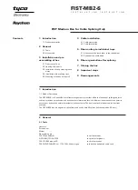
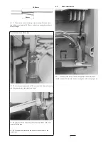
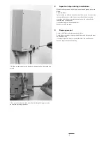
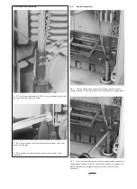
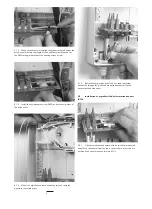
3.1.2 In case of a box with lock, lift cover and remove the guiding
pins.
3.2
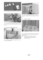
Opening of the cable ports
2.2
Kit contents
Depending on the network layout and the construction of the used
cables, the kit content may be different. Some of the components will
be pre-assembled in the box depending on the selection and the
ordering. The minimum content will be:
•
4 pcs of mounting bolts and plugs for wall mounting.
•
The box base
•
Pre installed
-
Universal Mounting System profile.
-
Small fiber routing block with tube holders
-
Tray lid and guiding pin and retainers
-
Velcro strap
-
FAS cap including the tray wedge
-
Cable strain relief connectors and fixing plate
-
patch panel with 2 anti movements strips
(AMS)
•
Cable glands, including pigtail seals (4 pigtails per seal)
•
Tiewraps
•
The Cover (including 4 preinstalled screws).
•
Installation instruction
2.3
Selection table
MB-2-T box capacity
W/A groove
Type of tray
max.number
Capacity
plate units
of trays
connectors KTUs
8
FIST-SOSA2-8SC-X
8
16
8
8
FIST-SOSA2-8SE-X
4
16
8
8
FIST-GB2-FOR04-XX-2
4
16
n/a
6
FIST-GB2-FOR08-XX-2
2
16
n/a
4
FIST-GB2-FOR12-XX-2
1
12
n/a
3
Installation
3.1
Preparation of box
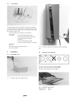
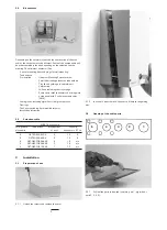
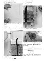
3.1.1 Unlock the screws and remove the cover.
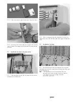
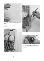
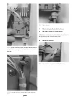
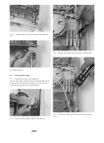
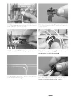
3.2.1 Drill out the ports to be used, (cable in, port 1 - pigtails out,
ports 2, 3, 4, 5).
1
2
3
4
5

