GPS Receiver A1030-A
5 Pin Out Information
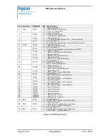
The functionality of the pins can be configured by software. This chapter describes
the pin out configuration with Tyco standard GPS firmware including the pin out for
a Dead Reckoning configuration and possible configurations with different inter-
faces.
5.1 Standard GPS and DR Firmware Configuration
5.1.1 Layout
Figure 5: Pin out information (bottom and top view)
Bottom view is showing the side of the module that will face the carrier board.
Page 14 of 37
User’s Manual
V2.0 - 07/05


