background image


GPS Receiver A1030-A 


12.10.3 HDLC 

The HDLC interface supports both the Telepass protocol and the European TC278 
DSRC communication standard. It supports Full Duplex operating mode with inde-
pendent baudrates for transmit/receive, including PLL for clock recovery. It features 
NRZ, NRZI, Manchester encoding, automatic bit stuffing, FCS generation and CRC 
check. Packets are stored in a local dual-port memory, for later retrieval by the 
CPU; this buffer is sized to hold a full HDLC frame, to minimize CPU load during the 
transaction. 
 

A1030A

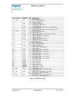
: The HDLC interface pins are realized in the following way: 

 
25: P1.4 - Transmit Buffer Active 
27: P1.5 - Oversampling Clock Out 
20: P1.13 - Reference Clock 
22: P1.14 - Receiver Data Input 
24: P1.15 - Transmit Data Output 
 

12.10.4 CAN 

The C-CAN consists of the components CAN Core, Message RAM, Message Han-
dler, Control Registers, and Module Interface. The CAN Core performs communica-
tion according to the CAN protocol version 2.0 part A and B. The bit rate can be 
programmed to values up to 1MBit/s. For the connection to the physical layer addi-
tional transceiver hardware is required. For communication on a CAN network, indi-
vidual Message Objects are configured. The Message Objects and Identifier Masks 
for acceptance filtering of received messages are stored in the Message RAM. 
 
All functions concerning the handling of messages are implemented in the Message 
Handler. Those functions are the acceptance filtering, the transfer of messages be-
tween the CAN Core and the Message RAM, and the handling of transmission re-
quests as well as the generation of the module interrupt. The register set of the C-
CAN can be accessed directly by the CPU via the module interface. These registers 
are used to control/configure the CAN Core and the Message Handler and to ac-
cess the Message RAM. 
 

A1030A

: The CAN signals CAN-TX and CAN-RX are realized on pins 18 and 16, 

respectively.


12.10.5 USB Slave Interface 

The USB_IP Peripheral provides an USB compliant connection between the host 
PC and the function implemented inside the ARM device. Data transfers between 
host PC and system memory occur through a dedicated packet buffer memory ac-
cessed directly by the USB_IP peripheral. This dedicated buffer memory must be 
sized according to the number of used endpoints and their related maximum packet 
sizes. In this implementation the dedicated memory is sized to 512 Byte and up to 8 

V2.0 - 07/05 

User’s Manual 

Page 31 of 37


Summary of Contents for A1030-A

Page 1: ...GPS Receiver A1030 A A description of Tyco Electronics GPS module A1030 A User s Manual Version 2 0 Hardware Revision 01...

Page 2: ...This page was intentionally left blank...

Page 3: ...nction ality new mechanical dimensions a few I O changes 1 2 18 11 04 Correct memory size additional products change in Dead Reckoning pin out 2 0 07 14 05 Detailed pin description new orientation of...

Page 4: ...STEMS WITHOUT THE EXPRESS WRITTEN APPROVAL OF TYCO ELEC TRONICS THIS DOCUMENT MAY PROVIDE LINKS TO OTHER WORLD WIDE WEB SITES OR RESOURCES BECAUSE TYCO ELECTRONICS HAS NO CONTROL OVER SUCH SITES AND R...

Page 5: ...TTFF 12 4 Mechanical Outline 13 4 1 Mechanical Overview 13 4 2 Connector 13 5 Pin Out Information 14 5 1 Standard GPS and DR Firmware Configuration 14 5 1 1 Layout 14 5 1 2 Description 15 5 2 General...

Page 6: ...n position fix pin 28 12 6 ENABLE pin low power mode 28 12 7 1PPS pin 1 pulse per second pin 28 12 8 Reset Signal 29 12 9 VBAT pin 30 12 10 Usage of additional interfaces 30 12 10 1 I2C 30 12 10 2 BSP...

Page 7: ...of the module are 4Mbit Flash and 2Mbit SRAM Operable at 3 3V 50mA 1fix per second Antenna link cable with SMA connector Antenna sensor pin with defined current sensing range for antenna detec tion o...

Page 8: ...nical dimensions Length Width Height 39 37mm 1 55 35 56mm 1 4 6 7mm 0 26 Weight 11g 0 4oz Table 1 A1030 A characteristics 1 The calibrated clock of the receiver has not stopped thus it knows precise t...

Page 9: ...A for the A1030 A module The xxx stands for the according firmware version Where 1xx is standard GPS software 2xx is GPS software with Dead Reckoning support The functionality of both software version...

Page 10: ...tion and evaluation kits 2 3 2 Development and Target Platforms V23993 DEV1030 A Development platform incl Rowley Toolset hardware interface adapter demonstration and evaluation board without LCD libr...

Page 11: ...t For details please refer to the ac cording chapters 3 1 Minimum Configuration The following picture shows a recommended minimum configuration for NMEA out put and commands received and sent via an R...

Page 12: ...GPS firmware is Serial 0 NMEA 4800 baud 8 data bits no parity 1 stop bit no flow control Serial 2 RTCM 4800 baud 8 data bits no parity 1 stop bit no flow control The default configuration within the...

Page 13: ...bottom view 4 2 Connector The power and I O connector used on the A1030 A is a 1 27mm 0 05 low profile double row socket with a height of 2 21mm 087 and a total of 50 contacts Po tential counterparts...

Page 14: ...standard GPS firmware including the pin out for a Dead Reckoning configuration and possible configurations with different inter faces 5 1 Standard GPS and DR Firmware Configuration 5 1 1 Layout Figur...

Page 15: ...DGPS 21 Tx2 Serial output 2 23 TEST0 Reserved for test purposes 29 Vgyro Input pin for gyro output voltage required for DR 33 LOCK Activated on LOCK position fix 37 GS Gain Select for LNA leave open...

Page 16: ...sults in a high gain 14dB This setting is recommended nRST Do not pull low when in low power mode 5 3 Free Configuration For custom specific applications all pins are more or less user definable The f...

Page 17: ...OOT 1 0 pins on exit from external Reset I O General Purpose I O I T1 ICAPA Ext Funct Timer 1 Input Capture A or External Clock 25 P1 4 I HTXACT HDLC Transmit Buffer Active I O General Purpose I O I T...

Page 18: ...lock I O General Purpose I O I O I1 SDA I2C Serial Data 22 P1 14 I HRXD HDLC Receive Data Input I O General Purpose I O 24 P1 15 O HTXD HDLC Transmit Data Output I O General Purpose I O 26 P2 8 I INT2...

Page 19: ...on for design ing an according main board The recommendations here assume the availability of a 5V VCC5D and 3 3V VCC3D digital power supply on this main board 6 1 Odometer and Reverse Signals Both si...

Page 20: ...cale factor 25mV deg s smaller values possible e g 12 5mV deg s at supply voltage 3V Important for system performance as well Temperature coefficient of scale factor max 10 at 30 to 80 C Linearity 0 5...

Page 21: ...This way oscilla tions of the power source affect the gyro and the ADC and therefore minimize the negative effects It is also recommended that Vcc3A is slightly below the power supplied to module Vcc...

Page 22: ...RAM 0x62000000 Table 8 External memory map A theoretical total of a memory space of 224 bytes corresponding to 16 Mbytes or 128 Mbit of SRAM and Flash respectively can be addressed Not existing memory...

Page 23: ...mA or 16mA Vcc 0 5V 0 Vcc 0 5V Output pins VOH VOL Vcc 0 8V 0 4V Input pins VIH VIL 0 7Vcc 0 3Vcc Table 9 Operating Conditions 8 2 Absolute Maximum Ratings Pin Description Min Max 3 Vcc 0 3V 3 6V Curr...

Page 24: ...0 05 low profile double row socket with a total of 50 contacts Potential counterparts on the motherboard are Harwin 1 27mm 0 05 micro strips of the M50 series For fixing the A1030 A on a motherboard...

Page 25: ...onnected to VANT If the antenna requires a different supply voltage the antenna bias can be provided through the VANT pin 10 2 Passive Antenna NOTE Different passive antenna set ups have been tested w...

Page 26: ...ceiver is preconditioned according to EIA JEDEC standard JESD22 A113 B Level 3 Basic qualification tests Temperature Cycling 40 85 C Temperature Humidity Bias 85 C 85 RH High Low Temperature Operating...

Page 27: ...r on GPS module The Antenna Sensor pin can detect when an active antenna is connected It can also detect when the antenna is short circuited or disconnected for some reason Please consider that the An...

Page 28: ...not necessary and will result in additional current draw 12 7 1PPS pin 1 pulse per second pin The 1PPS pin is an output pin In addition to precise positioning GPS also allows for accurate timing due t...

Page 29: ...e of value within a certain range 68 3 of all new values will be within 1 of the expected value 95 5 within 2 12 8 Reset Signal The nRST pin is an input pin The nRST pin can be used to generate a rese...

Page 30: ...onic Vespucci User Manual 12 10 1 I2C The I2C Bus Interface serves as an interface between the microcontroller and the external serial I2C bus It provides both multi master and slave functions and con...

Page 31: ...ation on a CAN network indi vidual Message Objects are configured The Message Objects and Identifier Masks for acceptance filtering of received messages are stored in the Message RAM All functions con...

Page 32: ...ic interrupt is generated reading status registers and or using different interrupt response routines the microcontroller can determine which endpoint has to be served which type of transaction took p...

Page 33: ...ovides Standard GPS Software that covers the following basic functions of a GPS module Standard GPS functionality Dead Reckoning capability WAAS EGNOS support Data logging For details please refer to...

Page 34: ...ady to go set This platform is also feasible as a target for custom specific developments With its standard JTAG interface programming toolsets by ARM RealView or Rowley CrossWorks for ARM can be used...

Page 35: ...are highly appreciated Hans Wiedemann Product Marketing Manager Positioning Products Tel 49 89 6089 838 Fax 49 89 6089 835 Tyco Electronics Corporation Power Systems Finsinger Feld 1 85521 Ottobrunn G...

Page 36: ...GPS Receiver A1030 A Page 36 of 37 User s Manual V2 0 07 05 This page was intentionally left blank...

Page 37: ...1 Environmental conditions 26 Table 12 1PPS signal characterization with active antenna with filter at 22 C 29 Table 13 1PPS signal characterization with passive antenna at 22 C 29 17 List of Figures...

Reviews: