


3.6.2
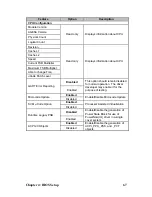
M1003 LED Control Board Connector Pin Definition
J1 USB Connector
Pin
Definition
Pin
Definition
1 VCC5 2 VCC5
3 USB1- 4 USB0-
5 USB1+ 6 USB0+
7 GND 8 GND
9 KEY
PIN
10 GND
J2 Front Panel Connector
Pin
Definition
Pin
Definition
1 HDLED+
2 HDLED-
3 RESET+
4 RESET-
5
6 PW_LED-
7 WLED+
8 WLED-
9 OCJ_SMBDAT
10 ICH_SMBCLK
11 EXT_INT
12 VOLTAGE5
13 V5SB
14 INTRU#
15
16 PWR_SW-
17 L 18 LAN1_LED-
19 L 20 LAN2_LED-
21 Reserve
22 Reserve
23
24 ID_LED-
25 ID_SW+
26 ID_SW+
27 KEY
PIN
28 NC
Chapter 3: Replacing Pre-Installed Components
55
Summary of Contents for Transport GT26-B4987
Page 1: ...Transport GT26 B4987 Service Engineer s Manual ...
Page 2: ......
Page 27: ...1 5 6 System Block Diagram Chapter 1 Product Overview 19 ...
Page 62: ...3 6 1 M1003 LED Control Board Features 54 Chapter 3 Replacing Pre Installed Components ...
Page 120: ...Registration Info Install Path SDP WSD Activation 112 ...
Page 121: ...Complete Custom Components Selection Only SDP or WSD may be installed Not both Below SDK 113 ...


