


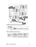


1.5.5
Jumpers & Connectors
Jumper/Connector
Function
J3
Front Panel Header (14Pin x 2)
J5
IPMB Pin Header (4Pin x 1)
J12
USB Pin Header (5Pin x 2)
J18
LCM Pin Header (3Pin x 2)
J29
FAN Tach Connector (9Pin x 2)
J35
M2061 PWR Connector (4Pin x 1)
J36/J37
SAS SGPIO Connector (3Pin x 2)
J38
SAS Fault LED Connector (5Pin x 2)
JP3/JP4
OPMA Setting Jumper (2Pin)
JP8
CMOS Clear (3Pin)
PWR6 Connector
PWR Connector for M1221(4Pin x 2)
Jumper Legend
OPEN - Jumper OFF
Without jumper cover
CLOSED - Jumper ON
With jumper cover
To indicate the location of pin-1
To indicate the location of pin-1
14
Chapter 1: Product Overview
Summary of Contents for Transport GT26-B4987
Page 1: ...Transport GT26 B4987 Service Engineer s Manual ...
Page 2: ......
Page 27: ...1 5 6 System Block Diagram Chapter 1 Product Overview 19 ...
Page 62: ...3 6 1 M1003 LED Control Board Features 54 Chapter 3 Replacing Pre Installed Components ...
Page 120: ...Registration Info Install Path SDP WSD Activation 112 ...
Page 121: ...Complete Custom Components Selection Only SDP or WSD may be installed Not both Below SDK 113 ...


