


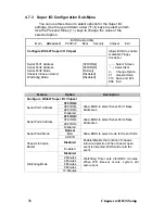


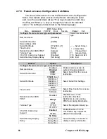
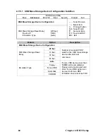


4.7.8 Remote Access Configuration Sub-Menu
You can use this screen to view the Remote Access Configuration
Menu. This feature allows access to the Server remotely via serial
port. Use the up and down arrow (
Ç
/
È
) keys to select an item. Use
the Plus and Minus (+/-) keys to change the value of the selected
option. The settings are described on the following pages.
BIOS Setup Utility
Main
Advanced
PCI/PnP Boot Security Chipset Exit
Configure Remote Access type and parameters
Remote Access
Serial Port Number
Base Address, IRQ
Serial Port Mode
Flow Control
Redirection After BIOS POST
Terminal Type
VT-UTF8 Combo Key Support
Serdir Memory Display Delay
[Disabled]
[COM1]
[115200 8,n,1]
[None]
[Always]
[ANSI]
[Enabled]
[NO Delay]
Select remote access
type.
←
→
Select Screen
↑↓
Select Item
+/- Change Field
F1 General Help
F10 Save and Exit
ESC Exit
Feature
Option
Description
Configure Remote Access type and parameters
Enabled
Remote Access
Disabled
Enables remote access to
system through serial port.
COM1
Serial Port Number
COM2
Select Serial Port for console
redirection.
115200 8, n,1
56700 8,n,1
38400 8,n,1
19200 8,n,1
Serial Port Mode
09600 8,n,1
Select Serial Port Settings..
None
Hardware
Flow Control
Software
Select Flow Control for console
redirection.
Disabled
Redirection After BIOS
POST
Always
Disabled: turns of the
redirection after Boot.
Redirection is active during
POST and during Boot loader.
ANSI
VT100
Terminal Type
VT-UTF8
Select the target terminal type.
Enabled
VT-UTF8 Combo Key
Support
Disable
Enable/Disable VT-UTF8
combination key support for
ANSI/VT100 terminals.
No Delay
Delay 1Sec
Delay 2Sec
Serdir Memory Display
Delay
Delay 4Sec
Gives the delay in seconds to
display memory information.
82
Chapter 4: BIOS Setup
Summary of Contents for Transport GT26-B4987
Page 1: ...Transport GT26 B4987 Service Engineer s Manual ...
Page 2: ......
Page 27: ...1 5 6 System Block Diagram Chapter 1 Product Overview 19 ...
Page 62: ...3 6 1 M1003 LED Control Board Features 54 Chapter 3 Replacing Pre Installed Components ...
Page 120: ...Registration Info Install Path SDP WSD Activation 112 ...
Page 121: ...Complete Custom Components Selection Only SDP or WSD may be installed Not both Below SDK 113 ...


