background image

SET-UP AND SAFE OPERATING PROCEDURES

6-17

89210007

Ref 

Stock 

Number

Part Number

Description

Image

6

2031-2225

WSP62180

Conductor Tube

7

2031-2228

WSPDR023

.023 Drive Roll Assembly

2031-2234

WSPGR023

.023 Guide Roll Assembly 

2031-2229 WSPDR035045 .035 Drive Roll Assembly 
2031-2235 WSPGR035045 .035 Guide Roll Assembly 

2031-2250 

WSPDRU023

.023 Drive Roll Assembly - U-Shaped 
Smooth

2031-2251

WSPGRU023

.023 Guide Roll Assembly - U-Shaped 
Smooth

2031-2252 WSPDRU035045

.035 Drive Roll Assembly - U-Shaped 
Smooth

2031-2253 WSPGRU035045

.035 Guide Roll Assembly - U-Shaped 
Smooth

8

2031-2233

WSPSCC

Spool Case Cover

9

2031-2232

WSPSC

Complete Spool Case

10 2031-2226

WSP62N

Conductor Tube Nut

11 2031-2231

WSP92

Trigger Assembly

NS

2031-2237

WSPMOTOR

Replacement Motor

2031-2239

WSPKEY

Key Stock for Drive Roll

Replacement Parts List

Summary of Contents for Spool gun

Page 1: ...Issue Date April 20 2012 Manual No 89210007 Revision A Safety and Operating Instructions SPOOL GUN English...

Page 2: ...help you to avoid potential hazards that may exist when working with this product YOU ARE IN GOOD COMPANY The Brand of Choice for Contractors and Fabricators Worldwide Tweco is a Global Brand of Arc...

Page 3: ...enton TX 76208 940 566 2000 www thermadyne com U S Customer Care 800 426 1888 International Customer Care 940 381 1212 Copyright 2011 2012 Thermadyne Industries Inc All rights reserved Reproduction of...

Page 4: ...ing wire feed pressure and speed 3 8 3 03 Installing the wire spool 3 8 SECTION 4 CARE AND MAINTENANCE 4 11 4 01 Changing the contact tip 4 11 4 02 Changing the wire conduit 4 12 4 03 Changing the dri...

Page 5: ...ctrical path All ground connections must be checked periodically to determine if they are mechanically strong and electrically adequate for the required current When engaged in AC welding cutting unde...

Page 6: ...e flying sparks hot slag and heated materials can cause fire and explosions Remove combustibles from the work area and or provide a fire watch Avoid oily or greasy clothing as a spark may ignite them...

Page 7: ...ion American National Standards Institute 1430 Broadway New York NY 10018 5 AWS F4 1 Recommended Safe Practices for Welding and Cutting Containers 6 AWS C5 3 Recommended Practices for Air Carbon Arc G...

Page 8: ...1 4 SET UP AND SAFE OPERATING PROCEDURES 89210007 This Page Intentionally Blank...

Page 9: ...ating Rated Welding Current C02 160A Duty Cycle 20 Wire Diameter Normal 0 023 0 035 Normal Wire Diameter Stainless Steel 0 023 0 030 Stainless Steel Maximum Wire Feed Speed 630 in min 16 m min Maximum...

Page 10: ...2 6 SET UP AND SAFE OPERATING PROCEDURES 89210007 This Page Intentionally Blank...

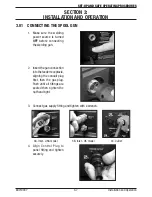
Page 11: ...ting the welding gun 2 Insert the gun connection into the feeder receptacle aligning the conduit plug first then the gas plug Push until all fittings are seated then tighten the nut hand tight 3 Conne...

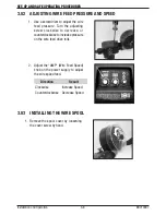
Page 12: ...lockwise to decrease or counterclockwise to increase pressure on the wire feed drive rolls 2 Adjust the AMP Wire Feed Speed knob on the power supply to adjust the wire speed feed Direction Result Cloc...

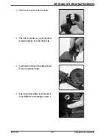
Page 13: ...onto the shaft 3 Press the red button on top of the gun to release pressure from the drive rolls 4 Push the wire through the guide and into the wire feed drive rolls 5 Make sure the welding power sou...

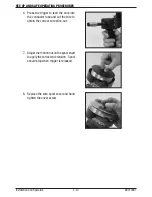
Page 14: ...nto the conductor tube and cut the wire to obtain the correct wire stick out 7 Adjust the friction nut on the spool shaft to apply the correct wire tension Spool should stop when trigger is released 8...

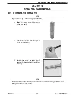
Page 15: ...med 1 Select the correct contact tip according to the wire used 2 Remove the nozzle from the gun to reveal the contact tip 3 Remove the contact tip using pliers if needed Replace contact tip and tight...

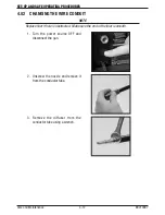
Page 16: ...UIT NOTE Replace liner if hole is obstructed Make sure the end of the liner is smooth 1 Turn the power source OFF and disconnect the gun 2 Unscrew the nozzle and remove it from the conductor tube 3 Re...

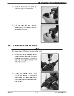
Page 17: ...ING THE DRIVE ROLLS NOTE Turn power supply OFF before replacing drive rolls 1 Remove the screws which secure the upper and lower drive rolls It may be necessary to remove drive roll side of gun case t...

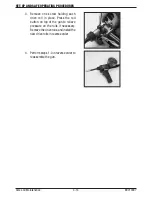
Page 18: ...holding each drive roll in place Press the red button on top of the gun to relieve pressure on the rolls if necessary Remove the drive rolls and install the new drive rolls in reverse order 4 Perform...

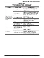
Page 19: ...until the wire feeds properly or doesn t slip See page 3 6 Worn or dirty drive rolls Clean or replace drive rolls Incorrect wire spool friction Adjust the friction nut on the spool shaft to find the...

Page 20: ...023 0 6 mm 1110 1101 11 30 Contact Tip 030 10 8 mm 1110 1102 11 35 Contact Tip 035 10 9 mm 2 1210 1300 21T 37 Nozzle 3 8 9 5 mm 1210 1100 21 37 Nozzle 3 8 9 5 mm 1210 1110 21 50 Nozzle 1 2 12 7 mm 12...

Page 21: ...Assembly 2031 2250 WSPDRU023 023 Drive RollAssembly U Shaped Smooth 2031 2251 WSPGRU023 023 Guide RollAssembly U Shaped Smooth 2031 2252 WSPDRU035045 035 Drive RollAssembly U Shaped Smooth 2031 2253 W...

Page 22: ...6 18 This Page Intentionally Blank...

Page 23: ...ion The remedies of the Purchaser set forth herein are exclusive and the liability of THERMADYNE with respect to any contract or anything done in connection therewith such as the performance or breach...

Page 24: ...ICAS Denton TX USA U S Customer Care Ph 1 800 426 1888 tollfree Fax 1 800 535 0557 tollfree Miami FL USA Sales Office Latin America Ph 1 954 727 8371 Fax 1 954 727 8376 Oakville Ontario Canada Canada...

Reviews: