TVLogic RKM Series Operation Manual Download Page 38

38 LCD Rack Mountable Monitor   
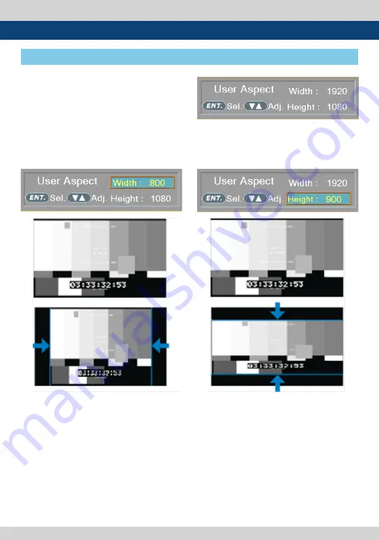
[1] User Aspect

7. Other Functions

•  Used to adjust the Width /Height display  

  ratio.  

1. Press the [Aspect] button on the front of the  

    monitor to activate the [USER ASPECT] mode. 

2. After the activation, press the [ENTER] button 

    to begin controlling. Adjust the ratio using  

    the [UP]/[DOWN] button.

- Adjust the ratio using the [UP]/[DOWN]   

 button.

- Control range for width : 

    * RKM-443A : MIN.0 , MAX 800

       RKM-356A : MIN.0 , MAX 1280

      RKM-270A : MIN.0 , MAX 1024

      RKM-290A : MIN.0 , MAX 1920 

- Control range for height : 

   * RKM-443A : MIN.0 , MAX 480

      RKM-356A : MIN.0 , MAX 800

     RKM-270A : MIN.0 , MAX 600

      RKM-290A : MIN.0 , MAX 1080

- The size-adjusted picture always stays in the  

  center of the screen.

- The size can be adjustable with 2 increment  

  and decrement.   

Summary of Contents for RKM Series

Page 1: ...LCD Rack Mountable Monitor RKM Series RKM 535A RKM 443A RKM 356A RKM 270A RKM 290A Operation Manual_v2 0 ...

Page 2: ......

Page 3: ...al may cause harmful interference to radio communications Operation of this equipment in a residential to correct the interference at his own expense CAUTION Change or modifications not expressly approved by the manufacturer responsible for compliance could void the user s authority to operate the equipment Disposal of Old Electrical Electronic Equipment Applicable in the European Union and other ...

Page 4: ...shock and or short internal parts For the same reason do not spill water or liquid on the product Do not attempt to repair the product yourself Removing covers can expose you to high voltage and other dangerous conditions Request a qualified service person to perform servicing If any of the following conditions occur unplug the power cord from the DC outlet and request a qualified service person t...

Page 5: ...nce they can block ventilation openings This product is not designed for built in installation do not place the product in an enclosed place such as a bookcase or rack unless proper ventilation is provided or the manufacturer s instructions are followed In the case of installing the product on a rack the inside of the product may be overheated due to the heat from other devices nearby and the decr...

Page 6: ...ontrol knob on the front of the monitor BLUE ONLY MONO Focus Assist H V delay Function Internal pattern generator 0 100 Gray Colorbar Pluge Markers Safety Areas C enter Marker Safety Area Marker Aspect Marker Display Size Scan 1 1 SCAN ZOOM Used to display the original image resolution without scaling to match a certain resolution or an aspect ratio This product supports Zoom function to enlarge t...

Page 7: ...Used to move within the menu when the OSD menu is activated and is also used to increase or decrease the value of selected feature ENTER Button Used to select the feature of main menu and the sub menus When the OSD menu is deactivated it will activated in orde of Bright Contrast Chroma Aperture After the function is actevated press DOWN UP button to adjust the values POWER Button Used to turn the ...

Page 8: ...dates and remote control Status Save Load LUT Save Load DC IN DC power input terminal for DC 12V Warning When using the product make sure to ground whenever possible before connecting the input signal cable in order to prevent any possible damage to the product or connected devices The damage may include signal noise malfunction of main board or display panel And the connected devices such as came...

Page 9: ...u Press the menu button more than 2sec input select menu will activated To change the input source press UP DOWN buttons to move and select the desired input UP DOWN Button Used to move within the menu when the OSD menu is activated and is also used to increase or decrease the value of selected feature ENTER Button Used to select the feature of main menu and the sub menus When the OSD menu is deac...

Page 10: ...gic Monitor control program Observer Ethernet port for easy firmware updates and remote control Status Save Load LUT Save Load DC IN DC power input terminal for DC 12V Warning When using the product make sure to ground whenever possible before connecting the input signal cable in order to prevent any possible damage to the product or connected devices The damage may include signal noise malfunctio...

Page 11: ...lected monitor among the monitor 1 2 3 If the signal is normal Green LED light is indicates If the signal is unsupported or disconnected LED light flashes in Yellow MENU Button Used to activate the OSD menu of the selected monitor among the monitor 1 2 3 When the OSD menu is activated press this button to exit from the menu UP DOWN Button Used to move within the menu when the OSD menu is activated...

Page 12: ...ontrol program Observer Ethernet port for easy firmware updates and remote control Status Save Load LUT Save Load ENTER F1 F2 SOURCE POWER SDI OUT DC IN USB SDI IN A HDMI IN CVBS REMOTE ETHERNET IN ETHERNET OUT SDI IN B RS 422 IN RS 422 OUT RKM 356A REAR DC IN DC power input terminal for DC 12V Warning When using the product make sure to ground whenever possible before connecting the input signal ...

Page 13: ...t Chroma Aperture After the function is actevated press DOWN UP button to adjust the values F1 F2 F3 F4 Button Lamp User can set the desired funtions in Function keys Used to activate the F1 F4 function AUDIO OUT Phonejack Used for Stereo Audio Output through Phone Jack video signals with embedded audio only TALLY Lamp Tally lamp that can be toggled in green or red using the REMOTE RJ 45 port or n...

Page 14: ...is terminal is used to upgrade the firmware or color calibration made by TVLogic ETHERNET IN OUT RJ 45 This terminal is used to control TVLogic Monitor control program Observer Ethernet port for easy firmware updates and remote control Status Save Load LUT Save Load DC IN DC power input terminal for DC 12V Warning When using the product make sure to ground whenever possible before connecting the i...

Page 15: ...Used to select SDI A SDI B input HDMI Button Lamp Used to select HDMI input CVBS Button Lamp Used to select CVBS input SCAN Button Lamp Used to change the scan mode Press the button to activate through the scan modes ZEROSCAN 1 1 SCAN USER ASPECT USER ASPECT User can adjust width and height of the display Check 7 Other Functions 1 User Aspect for more information ASPECT Button Lamp Used to change ...

Page 16: ...creen only under a blue signal Press the button again to activate mono mode WAVEFORM VECTOR Button Lamp Used to activate deactivate the Waveform The type of Waveform at work can be selected on the main menu F1 F2 F3 F4 Button Lamp User can set the desired funtions in Function keys Used to activate the F1 F4 function MENU EXIT Button Used to activate the OSD menu When the OSD menu is activated pres...

Page 17: ...r control program Observer Ethernet port for easy firmware updates and remote control Status Save Load LUT Save Load DC IN DC power input terminal for DC 12V Warning When using the product make sure to ground whenever possible before connecting the input signal cable in order to prevent any possible damage to the product or connected devices The damage may include signal noise malfunction of main ...

Page 18: ...n to activate the OSD menu 2 Move to a desired menu with the UP DOWN button 3 Press the ENTER button to select a menu and move to a sub menu with the UP DOWN button 4 Press the ENTER button to select the desired sub menu The selected sub menu will be highlighted 5 Press the ENTER button or the MENU button to save the new value after adjusting the value with the UP DOWN button 6 Press the MENU butt...

Page 19: ...f the monitor Color Temp Used to select the among preset color temperatures or adjust the customized color temperature of the monitor Preset color temperatures are 5600K 6500K 9300K and User1 2 3 In User 1 2 3 modes user can define custom RGB GAIN BIAS Offset and ColorCopy values Gain Red Green Blue The item controls red green blue gain value between 256 255 Only in User1 2 3 it is activated Bias ...

Page 20: ...rea Available sizes are 80 85 88 90 93 100 EBU ACTION 16 9 EBU GRAPHIC 16 9 EBU ACTION 14 9 EBU GRAPHIC 14 9 EBU ACTION 4 3 and EBU GRAPHIC 4 3 This function operates only after activating the Marker function Fit Marker Used to activate or inactivate the Fit Marker function When the Marker type is selected in the Marker menu a border line of the Safety Area will be displayed inside the Marker Imag...

Page 21: ... set to User User Marker H2 Used to set the position of the second horizontal marker line Displayed when Marker menu is set to User User Marker V1 Used to set the position of the first vertical marker line Displayed when Marker menu is set to User User Marker V2 Used to set the position of the second vertical marker line Displayed when Marker menu is set to User ...

Page 22: ... 88 SAFETY AREA 90 SAFETY AREA 93 SAFETY AREA 100 not supported in RKM 443A This item activates deactivates the REMOTE function The user may connect an RJ 45 jack to the REMOTE terminal on the rear of the unit and designate a function for each pin PIN 1 HDMI Channel PIN 2 SDI A Channel PIN 3 SDI B Channel PIN 4 Tally R PIN 5 Tally G PIN 6 Blue Only PIN 7 is POWER ON OFF use only PIN 8 is GND Funct...

Page 23: ...ming data of 8 characters and tally signal from TSL protocol D UMD TSL S16C Displays incoming data of 16charactersandtallysignalfromTSLprotocol V3 1 D UMD TSL D8C Displays incoming data of two pairs of 8 character strings and tally signals from TSL protocol UMD Character Customizes the characters for Under Monitor Display Alphabets numbers and special symbols are available Maximum of 8 characters ...

Page 24: ...tion activates in the same way as User Tally and Tally is displays by the Character color USER BG This function activates in the same way as User Tally and Tally is displays in the background of the character Tally1 Tally4 Color Used to set the color of each Tally 1 Tally 2 Tally 3 and Tally 4 Available colors are Red Green and Yellow B0 0 B1 0 B0 1 B0 1 The Byte0 Byte1 of TSL Protocol Control Byt...

Page 25: ... CONTROL BYTE bit 0 Tally 1 1 on 0 off bit 1 Tally 2 1 on 0 off bit 2 Tally 3 1 on 0 off bit 3 Tally 4 1 on 0 off bit 4 bright data Not used bit 5 bright data Not used bit 6 reserved Not used bit 7 cleared to 0 Not used DISPLAY DATA 16 displayable ASCII characters HEADER 1 BYTE CONTROL BYTE 1 BYTE DISPLAY DATA 16 BYTE Tally1 CHANNEL1 Tally2 Tally3 CHANNEL1 Tally4 ...

Page 26: ...1 1 0 CHANNEL1 1 1 CHANNEL1 The following appearance of UMD DISPLAY is set as D UMD D 8C D UMD TALLY TYPE and TALLY1 TALLY4 COLOR D UMD TALLY TYPE USER COLOR TALLY1 COLOR RED TALLY2 COLOR GREEN TALLY3 COLOR RED TALLY4 COLOR YELLOW CHANNEL1 CHANNEL1 Tally Type Default S 8C Single 8 Character S 16C Single 16 Character D UMD TALLY TPYE USER COLOR Color selections between TALLY1 TALLY4 D 8C Dual 8 Cha...

Page 27: ... Waveform and Vectorscope Waveform Vector The item sets Waveform and Vectorscope The operation order is WAVE FORM VECTOR SCOPE WAVE FORM WIDE WAVE FORM YCbCr WAVE_VECTOR FULL WAVEFORM Y FULL VECTORSCOPE Waveform Displays the shape and form of luminance level of a signal Vectorscope Displays color components of the input signals It is divided into 2 kinds depending on HD input and SD input 100 and ...

Page 28: ...een Color Pattern or Zebra Pattern Each pixel s Y analized and changed to a certain color or zebra pattern according to the Index on the right side of the screen When a pixel s Y level is under 0 16 the color diagonal line will be colored Green When the pixel s Y level is over 100 235 the color diagonal line will be colored Red When the Y level of a pixel is between 0 100 the pixel is displayed wi...

Page 29: ... or not to activate Y MAX Y MIN C MAX C MIN Y PICTURE BLINK and C PICTURE BLINK functions The values of Y MAX Y MIN C MAX C MIN are indicated in Waveform Vectorscope If Y PICTURE BLINK or C PICTURE BLINK is enabled the section of image that exceeds the selected values of Y MAX Y MIN C MAX and C MIN shall blink In the case of RGB input Range Error is not supported See section 7 Other Functions 7 Ra...

Page 30: ... audio Available options are OFF 16 CH HOR and 16 CH VER 16 CH HOR Displays 8 channels on top left and 8 channels on top right of the screen horizontally 16 CH VER Displays 8 channels on center left and 8 channels on top right of the screen vertically In the HDMI mode only 2 channels may be displayed Level Meter Display Used to set the display method for audio level meter Available modes are Group...

Page 31: ... signals Blue Only Used to activate MONO mode or remove red and green from the input signal and display the screen only under a blue signal Activates in the order Off Blue Only Mono Off User Aspect Horizontal Used to set the Horizontal size of the screen Activates only when the SCAN mode is set to USER ASPECT User Aspect Vertical Used to set the Vertical size of the screen Activates only when the ...

Page 32: ...on Available modes are OFF 708 608 LINE21 and 608 ANC 608 CEA 608 B 708 CEA 708 C standard display only Zoom Not supported in RKM 535A Used to magnify the image up to 90 on a pixel basis and display on full screen ex 10 ZOOM When the input signal is 1920x1080 it wil enlarge 10 missing 1728 H x 976 V displays the area of 1728 H x 976 V to the full screen See section 7 Other Functions 4 Zoom for mor...

Page 33: ... the firmware using USB Thumb drive See section 7 Other Functions 9 Firmware Upgrade for more information S W upgrade start Used to start S W upgrade If USB drive is detected the firmware upgrade becomes activated See section 7 Other Functions 9 Firmware Upgrade for more information Firmware Version The item shows current firmware version 5 Menu Operations ...

Page 34: ...isplays after selecting the desired input mode check and make sure that your connection is not lose or disconnected RKM Series monitors support CVBS Input signal 1 Press the SOURCE or CVBS button on the front of the monitor and activate the OSD menu as shown on the below Move to desired input signal by scrolling the knob or UP DOWN buttons 2 Input resolution displays on the bottom of the OSD scree...

Page 35: ... selecting the desired input mode check and make sure that your connection is not lose or disconnected RKM Series monitors Support HDMI Digital input signal 1 Press the SOURCE or HDMI button on the front of the monitor and activate the OSD menu as shown on the below Move to desired input signal by scrolling the knob or UP DOWN buttons 2 Input resolution displays on the bottom of the OSD screen 3 P...

Page 36: ...ress the function button F1 F4 on the front of the monitor for more than 2 seconds and activate the OSD menu as follows 2 Move to a desired function with the UP DOWN button or Knob and press the ENTER button to select 3 Once the function is set press the Function button F1 F4 to activate the function RKM 356A 270A 290A RKM 443A ...

Page 37: ... image Zero Scan Magnifies or reduces the original image and displays it without loss of the ratio of the image 2 1 Scan Magnifies the original image double and displays it only when the original image size is smaller than a half of the screen size 1 1 Scan Displays the original image in 1 1 ratio on the screen When the original image is bigger than the screen only center part of the original imag...

Page 38: ...trolling Adjust the ratio using the UP DOWN button Adjust the ratio using the UP DOWN button Control range for width RKM 443A MIN 0 MAX 800 RKM 356A MIN 0 MAX 1280 RKM 270A MIN 0 MAX 1024 RKM 290A MIN 0 MAX 1920 Control range for height RKM 443A MIN 0 MAX 480 RKM 356A MIN 0 MAX 800 RKM 270A MIN 0 MAX 600 RKM 290A MIN 0 MAX 1080 The size adjusted picture always stays in the center of the screen The...

Page 39: ...scopes are displayed according to SD or HD input signals 100 and 75 scales are indicated on the Vetorscope Waveform Cb Cr Displays the Cb Cr components of the input signal into waveform The Waveform Vectorscope function can be used only when the input signal is YUV In the case of RGB input Waveform RGB is supported Available modes in the YUV signal Waveform Y Vectorscope Waveform Wide Waveform Y C...

Page 40: ...Select Line Position and use the UP DOWN button to select a vertical line Selected line is indicated in White on the screen Control range varies according to the resolution of the input SDI signal PAL 0 625 NTSC 0 525 720p 0 750 1080 i p 0 1125 Control range for HDMI signal varies according to the output resolution of the signal 4 Zoom Used to magnify the input signal from 0 to 80 Supports Zoom Wi...

Page 41: ...color is assigned to pixels with Y level from 70 to 75 Yellow color is assigned to pixels with Y level from 75 to 85 and Cyan from 60 to 70 This function is designed for a better performance in setting the exposure of lighting when shooting with vDSLR cameras Zebra Pattern Type Displays the pixels with designated Luma Y levels with zebra pattern Y 100 Pixels with Y level over 100 turn into red dia...

Page 42: ...ith a shallow depth of field Available types are Mono and Color types Mono Background image is mono type Color Background image is original color type Pixels with Y or C levels exceeding the designated levels of Y MAX Y MIN C MAX and C MIN shall blink Analyzes the input signal s Luma Y and chroma information C and if the input signal exceeds the designated minimum value and maximum value the pixel...

Page 43: ... Functions 8 Internal Pattern Color Bar Pluge Pattern Gray Pattern Displays internally generated test patterns The pattern consists of ColorBar and Pluge Grayscale Patterns Full screen colors of various gray levels 0 100 are also embedded ...

Page 44: ...rrectly S W upgrade start is activated if the item is not activated please disconnect and connect the USB memory stick again After 5 sec do the same procedure The monitor searchs USB memory stick Select Yes in S W upgrade start and proceed the firmware update During the update the monitor screen is off and nothing functions After the update TVLogic logo shows up on the screen and the monitor initi...

Page 45: ...d Video mode In DVI ANALOG DIGITAL mode ZERO scan must be selected for normal function If the input image is in non wide mode press ASPECT button to change to wide display Resolution Frequency 640 X 480 60Hz 75Hz 800 X 600 60Hz 72Hz 75Hz 1024 X 768 60Hz 70Hz 75Hz 1366 X 768 60Hz 75Hz 1280 X 1024 60Hz 75Hz 1600 X 1200 60Hz 1920 X 1080 60Hz SMPTE 274M 1080i 60 59 94 SMPTE 296M 720i 60 59 94 SMPTE 12...

Page 46: ...70Gbps HD SDI 1 485Gbps SD SDI 270Mbps HDMI Analog Input Spec Composite 1 0Vpp With Sync SDI Input Signal Formats SMPTE 425M A B 1080p 60 59 94 50 30 29 97 25 24 23 98 30sF 29 97sF 25sF 24sF 23 98sF SMPTE 274M 1080p 30 29 97 25 24 24sF 23 98 23 98sF 50 59 94 60 1080i 60 59 94 50 SMPTE 296M 720p 60 59 94 50 SMPTE 260M 1035i 60 59 94 SMPTE 125M 480i 59 94 ITU R BT 656 576i 50 Audio In Audio Out Powe...

Page 47: ...30 29 97 25 24 24sF 23 98 23 98sF 50 59 94 60 1080i 60 59 94 50 SMPTE 296M 720p 60 59 94 50 SMPTE 260M 1035i 60 59 94 SMPTE 125M 480i 59 94 ITU R BT 656 576i 50 Audio In Audio Out Power DC 12V Power Consumption Approx 60 Watts DC Max 3A Operating Temperature 0 to 35 32 to 95 Storage Temperature 20 C to 60 C 4 F to 140 F Main Body Dimensions mm inch 465 X 82 5 X 83 31 18 31 X 3 25 X 3 30 Main Body ...

Page 48: ...5 24 24sF 23 98 23 98sF 50 59 94 60 1080i 60 59 94 50 SMPTE 296M 720p 60 59 94 50 SMPTE 260M 1035i 60 59 94 SMPTE 125M 480i 59 94 ITU R BT 656 576i 50 Audio In Embedded Audio Analog Stereo Phone Jack Audio Out Analog Stereo Phone Jack Speaker Mixed mono Power DC 12V Power Consumption Approx 60 Watts DC Max 3 7A Operating Temperature 0 to 35 32 to 95 Storage Temperature 20 C to 60 C 4 F to 140 F Ma...

Page 49: ...4 24sF 23 98 23 98sF 50 59 94 60 1080i 60 59 94 50 SMPTE 296M 720p 60 59 94 50 SMPTE 260M 1035i 60 59 94 SMPTE 125M 480i 59 94 ITU R BT 656 576i 50 Audio In Embedded Audio Analog Stereo Phone Jack Audio Out Analog Stereo Phone Jack Speaker Mixed mono Power DC 12V Power Consumption Approx 60 Watts DC Max 2 5A Operating Temperature 0 to 40 32 to 104 Storage Temperature 20 C to 60 C 4 F to 140 F Main...

Page 50: ... 24sF 23 98 23 98sF 50 59 94 60 1080i 60 59 94 50 SMPTE 296M 720p 60 59 94 50 SMPTE 260M 1035i 60 59 94 SMPTE 125M 480i 59 94 ITU R BT 656 576i 50 Audio In Embedded Audio Analog Stereo Phone Jack Audio Out Analog Stereo Phone Jack Speaker Mixed mono Power DC 12V Power Consumption Approx 60 Watts DC Max 2 8A Operating Temperature 0 to 40 32 to 104 Storage Temperature 20 C to 60 C 4 F to 140 F Main ...

Page 51: ......

Page 52: ...53 802 서울특별시 금천구 가산동 345 4 에이스하이엔드 8차 12층 FOR MORE INFORMATION PLEASE VISIT http www tvlogic tv 12F ACE HIGH END 8 84 Gasan digital 1 ro Geumcheon gu Seoul 18590 KOREA TEL 82 70 8668 6611 FAX 82 2 6123 3201 E mail sales tvlogic co kr ...

Reviews: