Hangzhou Tuya Inc.
NM1 Module Hardware Design Manual
https://www.tuya.com
Page 19 of 29
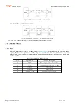
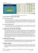
Figure 3- 7 Reference circuit with a level converter
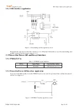
A triode can also be used for level conversion.
Figure 3- 8 Reference circuit with a triode for level conversion
Note: Connection methods of the debugging, auxiliary, and primary serial interfaces are similar.
3.8 USB Interface
3.8.1 Pins
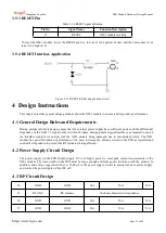
The NM1 module has a USB 1.1 interface, which
can only be used
for module upgrade. If ESD design is
required, the maximum capacitance of ESD components must be less than 0.5 pF. Otherwise, waveform
distortion may occur, affecting bus communication. The differential impedance of differential data cables must
be within 90 ohms.
Table 3- 8 USB interface signal definition
Pin No.
Signal Name
Function Description
17
RXD
Receiving over the serial interface
18
TXD
Transmission over the serial interface
21
USB_DP
USB+ signal
22
USB_DM
USB– signal
63
AVDD33_VUSB
Internal USB power supply

