background image

31

Operative Instructions

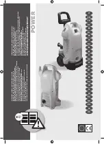
21) End of the «STANDARD» cycle. Open the door and 

remove the rack.

Fig. 18.22

If, for any reason, it is necessary to interrupt the cycle, 

simply hold down the RESET key for a few seconds until 

an audible alarm (buzzer) is heard and an alarm screen 

appears on the display.
Once the problem is resolved, resume the cycle from 

the beginning. If the problem cannot be solved, contact 

the technical assistance. 

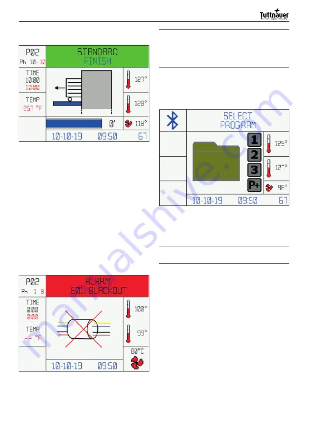
7.2.5  Alarm messages

The  machine  is  equipped  with  an  alarm  system  that 

indicates  malfunctions  detectable  with  an  audible 

signal (buzzer), a screen on the graphic display of the 

control panel and a red led light in the camber.
At first the image concerning the alarm is displayed (for 

5 seconds); then the alarm description is displayed (for 

10 seconds).
The image and text alternate until the alarm is reset.

Fig. 19

If the program is interrupted because of an alarm, the 

display  will  show  the  message  «Program  interrupted 

stop-alarm». Follow the message shown on the display 

to reset the alarm. 


Ö

IMPORTANT  NOTE!  If  the  RESET  button  is 

pressed during the wash cycle, the program 

is interrupted and an alarm is displayed with 

the message 

«Program  interrupted

  stop  - 

user

»

. Press RESET to return to initial display.

For the alarms, description and possible solutions see 

Annex 12.6.

7.2.6  User settings menu

Start screen

Fig. 20.1

To access the settings menu the procedure is as follows: 

Open door  -> PRG key for 5 seconds -> If the user and 

password are enabled, insert user password.


Ö

IMPORTANT NOTE! USER PIN MANAGEMENT 

option on request. 

The  keys  and  their  operation  are  shown  below, 

contextualised  according  the  menu  in  which  you  are 

located:

 - Use P1 and P2 to navigate up and down the menu.

 - Press START to access the entry of the menu selected.

 - Within the parameter, use the 1 and 2 keys to change 

the value of the highlighted parameter.

 - Press START to go to the next parameter.

 - Press PRG to return to the previous menu.

Summary of Contents for TIVA8-L

Page 1: ...o operate with the glassware washer read these instructions for use INSTRUCTIONS FOR USE Original instructions Code Man205 0746009EN Rev 02 Edit 06 2022 Language English Firmware version 00B03 GLASSWA...

Page 2: ...e due to negligence and failure to comply with this manual and is also not liable for any damage caused by incorrect interpretations of the instructions contained Check for any updates to this manual...

Page 3: ...of glassware 23 6 3 Programs 23 6 3 1 Suggested programs vs configurations 23 6 3 2 Program structure 23 6 4 Starting the machine 23 6 4 1 Before starting the program 23 6 4 2 Starting the program 24...

Page 4: ...asher features The same personnel must store it and keep it intact to allow its consultation throughout the life span of the machine itself The personnel in charge must strictly and diligently follow...

Page 5: ...m sunlight Symbol Description Keep dry Please read this user manual carefully before commissioning the device The product complies with UL safety standards valid for both Canada and the USA For the di...

Page 6: ...which is available to ensure prompt and accurate technical assistance and everything necessary for restoring the full efficiency of the product All disputes arising from or in connection with these Te...

Page 7: ...O 12100 IEC 61010 1 IEC 61326 1 2006 42 EC 2014 30 EC 2011 65 EC The machine does not cause harmful vibrations The residual radiation emitted within the limits is non ionizing The shelf life cycle of...

Page 8: ...Protection Against ingress of solid foreign objects 12 5 mm diameter Against ingress of water with harmful effects 0 non protected CE marking Directive 2006 42 CE 2014 35 UE At the end of each cycle a...

Page 9: ...r It is suitable for use as a chemical s tank storage compartment Fig 4 For installing the stand 1 Raise the machine and place it on top of the stand 2 Open the stand s door and install the stand on t...

Page 10: ...here patients are housed The machine can heat the environment thus increasing humidity 3 1 3 Operator obligations Before starting to operate for the first time become familiar with the control devices...

Page 11: ...leted the safety devices reactivated and the guards reassembled It is strictly forbidden to remove or tamper with the safety devices The machine maintenance must only be performed with the power suppl...

Page 12: ...d outside the packaging Fig 6 that indicates A Minimum and maximum temperature of the storage environment B Minimum and maximum humidity of the storage environment C Minimum and maximum pressure of th...

Page 13: ...trical and water connections loading unloading can only be carried out by specialised and authorised personnel and by consulting the relative diagrams Before machine positioning make sure that All the...

Page 14: ...ventions The machine must be supplied with current whose voltage frequency and protection values correspond to those indicated on the data plate Additional indications regarding the electrical connect...

Page 15: ...ion the machine must be equipped with an internal softener option available The water used in all the washing stages should be of drinking quality according to the Guidelines for drinking water qualit...

Page 16: ...not be shortened or damaged The water supply taps must be capable of quickly stopping the water line therefore they must be equipped with a ball or a gate valve They must also withstand the operating...

Page 17: ...1 5 lbs 0 7 kg of salt 6 Thoroughly clean the edge of the salt tank 7 Tighten the cap again 8 Run a Prewash program to clean the salt residues inside the wash chamber It is absolutely necessary to rem...

Page 18: ...n must be properly installed according to the applicable instructions b HAZARD If the waste connection is installed incorrectly the waste water could flow backwards into the machine s chamber 5 4 2 Wa...

Page 19: ...the type of liquid to be used for each suction tube IMPORTANT NOTE Spray arm assembly direction the water outlet holes must face towards the inside of the chamber otherwise the spray arms will NOT wo...

Page 20: ...he actual dosing of the chemical exceeds the tolerance of 5 the system goes into alarm Standard pre installed chemicals IMPORTANT NOTE If the machine does not use these recommended liquids the flow me...

Page 21: ...5 Release the button and repeat the sequence from 3 to 4 for the other dosing pumps that need to recharge the hydraulic circuit 1 2 3 4 8 7 6 5 Fig 13 CAUTION This phase must be performed at the firs...

Page 22: ...t fall off the racks and inserts and do not hang from the grid bars Check that injector nozzles and connectors are securely held in position in the baskets or inserts Insert the glassware into the app...

Page 23: ...oride hydrochloric acid etc The air and spray channels must be clean Finally carry out a test Use the recommended liquids see chapter Using and Storing Chemicals 6 3 Programs The machine leaves the fa...

Page 24: ...heats up until it reaches the specific temperature for the selected program a temperature that remains stable for the holding time The cleaning liquid is automatically introduced before the start of t...

Page 25: ...Panel The control panel consists of 8 keys and a 3 5 inch LCD display All keys except key 3 are multi function depending on the action being performed in a specified state of the device 1 2 3 4 8 7 6...

Page 26: ...ity value in microsiemens if conductivity probe function is enabled 4 Several animated images showing the current status of the machine are displayed 5 The elapsed phase time from the moment the tempe...

Page 27: ...must be tightly closed until you hear the classic closing click otherwise the program will not start Fig 18 1 2 With the machine started and door closed the screen for selecting the programs will app...

Page 28: ...nt in the chamber Fig 18 6 Phase 2 6 Self loading of cold water During the self loading phase the chamber will be filled Fig 18 7 7 Prewash phase begins Fig 18 8 Phase 3 8 At the end of the prewash ph...

Page 29: ...t Fig 18 12 Phase 5 12 At the end of the wash phase the water is automatically discharged Fig 18 13 Phase 6 13 Self loading of hot water During the self loading phase the chamber will be filled Fig 18...

Page 30: ...end of the phase if the conductivity will be below a presetted value the machine will procede to the next phase If the check is negative the machine will repeat phases 7 and 8 again If the second che...

Page 31: ...upted because of an alarm the display will show the message Program interrupted stop alarm Follow the message shown on the display to reset the alarm IMPORTANT NOTE If the RESET button is pressed duri...

Page 32: ...and select the desired language from those available 7 2 9 USB key management When the USB key is hooked up in the machine the following message appears after a few seconds Fig 21 1 When the USB key...

Page 33: ...value files CSV for post processing activities free files editables with third part softwares like MS Excel IMPORTANT NOTE The software comes with a free one week 7 days trial period at the end of the...

Page 34: ...tted PRP Washing pump pressure Transmits the status of the wash pump VDP1 VDP2 VDP3 VDP4 VDP5 Quantity of product delivered This code is reset every time a phase of the program ends VCW VHW VDW Quanti...

Page 35: ...er of operating hours the display shows MAINTENANCE This signal has no influence on the machine operation contact the customer service or the dedicated technical assistance for periodic maintenance a...

Page 36: ...Remove the mesh filter 2 Fig 11 4 Remove the chamber bottom filter 3 Fig 11 5 Carefully clean the filters and remove the residual substances 6 Remove the deposits from the drain and clean the drain 7...

Page 37: ...the laws in force in the country of use of the machine in relation to the use and disposal of the products used for the cleaning and maintenance of the machine as well as observe what the manufacturer...

Page 38: ...hough dedicating particular care to this service is not liable for any shipping delays due to force majeure Shipping costs are always charged to the recipient Goods travel at the risk and danger of th...

Page 39: ...isables hot water If hot water is enabled purified water is automatically deactivated and vice versa OFF 8 User PIN enable at the start of cycle 0 OFF 1 ON Available only with User PIN Management opti...

Page 40: ...Set password expiration time 6 22 User PIN enable at the end of cycle 0 OFF 1 ON Available only with User PIN Management option Enables or disables user PIN at the end of cycle OFF 23 Upper Spray Arm...

Page 41: ...N Enables or disables the product 2 flowmeter ON 11 Product 3 enable 0 OFF 1 ON Enables or disables the product 3 pump ON 12 Product 3 flowmeter 0 OFF 1 ON Enables or disables the product 3 flowmeter...

Page 42: ...program 6 Program cycles 40 Number of cycles performed with program 40 USER PIN 1 Pin User 1 To set the user password press the RESET key and enter the 6 desired numbers 2 Pin User 2 3 4 Pin User 20...

Page 43: ...suming mode Program bu on 1 Program bu on 2 Program bu on 3 Printer language Drying enable Lower Spray Arm White LED always ON Fahrenheit temperature PIN expira on month User PIN enable at the end of...

Page 44: ...password change D O P S 3 Select User User Blocked Press Start to con rm P D P D P D P D P D P D Y N N Y N Enter old password Enter new password Con rm new password The password has been changed corr...

Page 45: ...r user S P P 5 Select User Pin menu Insert Super User password max 3 a empts Digit password is valid is expired or rst access See password change procedure for Super User P D P D P D N N Y Y Select Us...

Page 46: ...word expired Press Start to con rm N N Enter old password Enter new password Con rm new password The password has been changed correctly Is valid Is it equal to old password Y Y N Y S P P 5 Insert Sup...

Page 47: ...NO COLD WATER The cold water tap could be closed or partially open Check it Check if the safety floatswitch has not tripped Press RESET If it persists call the service personnel E21 NO HOT WATER The h...

Page 48: ...E46 AIR T LIMIT A too high air temperature was detected Press RESET If it persists call the service personnel E47 PHASE T LIMIT A too high temperature was detected during the current phase Press RESET...

Page 49: ...personnel E80 SPRAY ARM LOCKED The spray arm marked in red on display is locked Remove it and clean Press RESET If it persists call the service personnel 12 7 Warnings table WARNING TYPE DESCRIPTION...

Page 50: ...w 4 The operating temperature for the program is not reached The thermostat sensor in the washing chamber is covered with deposits Clean the thermostat sensor 5 The machine does not dry The air filter...

Page 51: ...PT1000 2 temperature chamber control probe C Yes 0 3 1 0 31 0 17 18 19 20 TPT3 PT1000 3 temperature air probe C Yes 0 1 0 4 104 21 22 23 24 ERR Alarm number n Yes 0 0 7 0 70 25 26 27 28 29 30 CYC Coun...

Page 52: ...0 0 6 6 71 72 73 74 CONP Conductivity probe status n Yes 0 0 0 2 2 75 76 77 78 79 A0 A0 Value n Yes 0 6 1 8 0 6180 80 81 82 83 SPRYR B Spray arm at the bottom of the chamber rotation monitoring rpm Y...

Page 53: ...0 Program 40 PHA TYPE PHASE IN EXECUTION 0001 Drain 0010 Trolley insertion 0002 Prewash 0011 Door closure 0003 Wash 0012 Program selection 0004 Rinse 0013 Operator scan 0005 Disinfection 0014 Trolley...

Page 54: ...150 150 ml of product delivered VCW VHW VDW QUANTITY OF WATER DELIVERED 0000 0 liters of water delivered liters of water delivered 0001 1 liter of water delivered 0012 12 liters of water delivered CON...

Page 55: ...55 Operative Instructions...

Page 56: ...Tuttnauer USA Co Ltd 25 Power Drive Hauppauge N Y 11788 USA Tel 1 631 737 48 50 1 800 624 58 36 Fax 1 631 737 07 20...

Reviews: