background image

Now turn the board over. The easiest way, without all the sockets falling out, is to take a 
ruler and put it on top of the sockets, hold it with the PCB and turn it around. When you 

put it on the table, you can slide the sockets and PCB off the ruler.

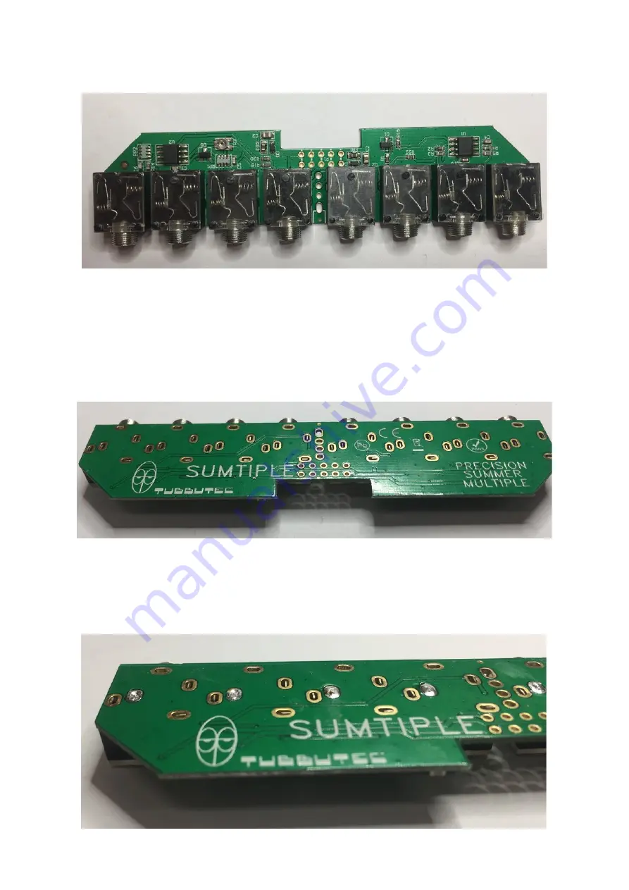
If you cut the pins to the right length, the PCB with the sockets should look something like 
this:

You can see that the pins are level with the PCB and not sticking out (This should be the 
case for every pin on the board [the LED and pin header pins])  Now start soldering one pin 

of each jack. That makes it easier to realign them before soldering the rest of the pins.
We used the second pin from the left in the picture above.

Summary of Contents for Sumtiple

Page 1: ...eter for calibration Small screwdriver Construction First you should start with preparing the parts needed for proper construction Check the pictures for a better understanding of what needs to be done First take the jack sockets you need to pinch off a little of each pin The pins need to be cut to a length of 1mm If they are not short enough they will stick out of the board and may touch a module...

Page 2: ...off the ruler If you cut the pins to the right length the PCB with the sockets should look something like this You can see that the pins are level with the PCB and not sticking out This should be the case for every pin on the board the LED and pin header pins Now start soldering one pin of each jack That makes it easier to realign them before soldering the rest of the pins We used the second pin f...

Page 3: ...he other wires so that they are 2 5mm apart from each other Now you can fit the LED to the PCB note for a better overview the sockets are not yet placed in the pictures it is VERY IMPORTANT that the sockets are placed first Solder the shortest pin then pinch off all pins as close to the PCB as possible Make sure the LED sits properly on the board like on the right picture Now solder the other pins...

Page 4: ...rd should look like this now You can take the front panel attach it to the board and screw the nuts to the jacks Note the correct orientation of the front panel You only need to calibrate the Sumtiple for the high precision and you are done ...

Page 5: ... voltage such as 5V but that may result in a more difficult calibration Attach the voltage source to the first summing inputs and measure the voltage between the input and the summer output with a multimeter preferably in mV range Adjust the trimmer on the PCB until the voltage reads as close to 0V as possible The three summing inputs will have slightly different gains variation of maximum 0 05 so...

Reviews: