Use as little solder as possible or cut/pinch off the solder afterwards, so it looks like above.
Check if the jacks are aligned, then you can solder the pins that are left, again, try to use as
little solder as possible.
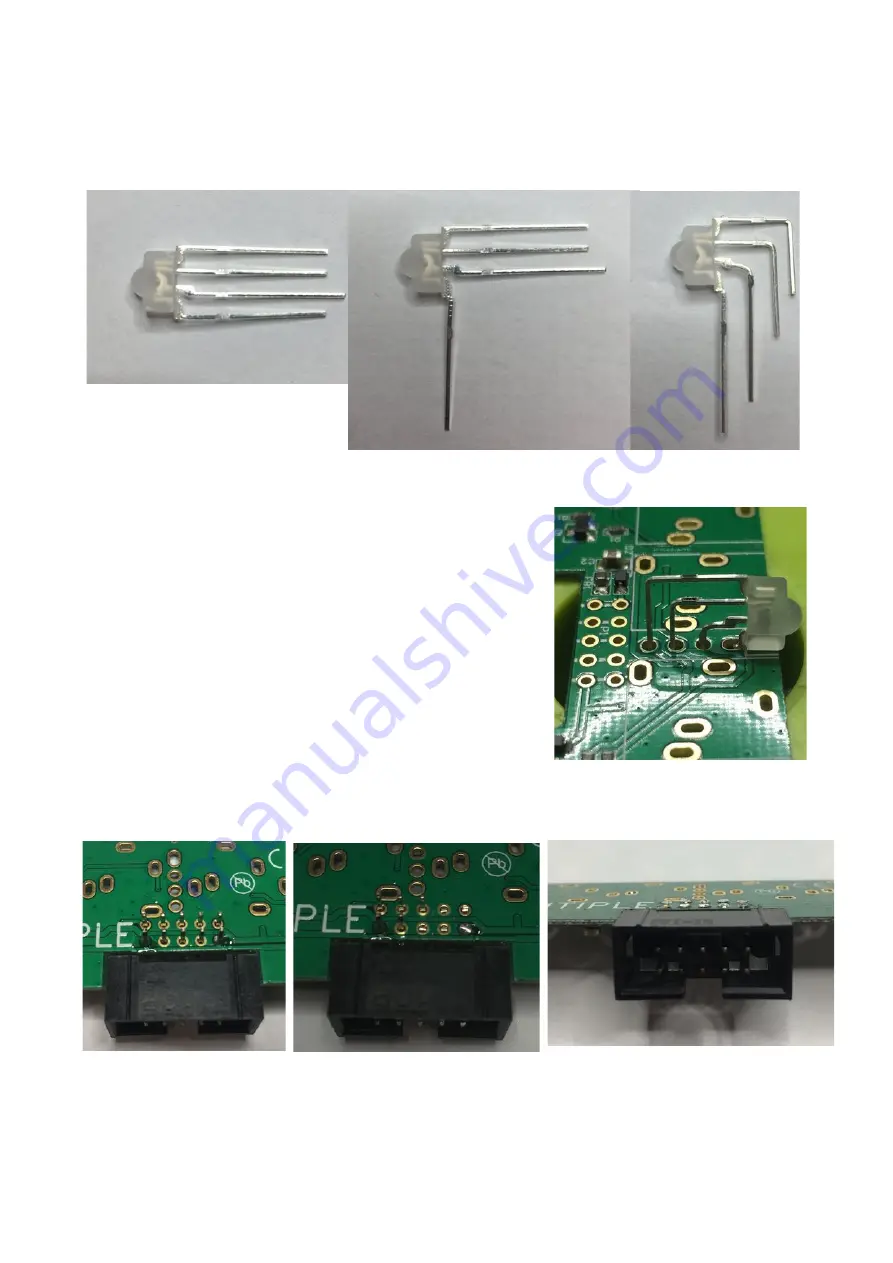
Now take the RGB-LED. You need to bend the wires in a 90° angle for the LED to fit.
The flat side is looking towards you, note that one wire that is longer than the other three.
The wire underneath it must be bend as near to the plastic part as possible.
Now you need to bend the other wires, so that they are
2.5mm apart from each other.
Now you can fit the LED to the PCB (note: for a better
overview the sockets are not yet placed in the pictures, it is
VERY IMPORTANT that the sockets are placed first!). Solder
the shortest pin, then pinch off all pins as close to the PCB
as possible. Make sure the LED sits properly on the board
like on the right picture. Now solder the other pins.
You can now place the 10-Pin-Header. Make sure it aligns with the board and solder two
pins on every corner. Pinch off all pins so they only stick out a little.
After pinching off the pins and soldering them, the pin header and the PCB should now
look something like the right picture above.


