background image


 Installation and Usage


1.  Recommended shaft tolerance is shown below. Interference fit and shrink fit are prohibited for clutch fixing. 


Clutch Bore 

Shaft Fit Guide 

1.20 to 2.00 inches dia. 

30mm to 50mm dia. 

Line fit to .0010 inches loose 

(0.025mm) 

2.00 to 3.15 inches dia. 

50mm to 80mm dia. 

 Line fit to .0012 inches loose 

(0.030mm) 

3.15 to 4.70 inches dia. 

80mm to 120mm dia. 

Line fit to .0014 inches loose 

(0.036mm) 

4.70 to 7.10 inches dia. 

120mm to 180mm dia. 

Line fit to .0016 inches loose 

(0.041mm) 

7.10 to 9.85 inches dia. 

180mm to 250mm dia. 

Line fit to .0018 inches loose 

(0.046mm) 

9.85 to 12.40 inches dia. 

250mm to 315mm dia. 

Line fit to .0020 inches loose 

(0.051mm) 

12.40 to 15.70 inches dia. 

315mm to 400mm dia. 

Line fit to .0023 inches loose 

(0.058mm) 

15.70 to 17.72 inches dia. 

400mm to 500mm dia. 

Line fit to .0025 inches loose 

(0.064mm) 


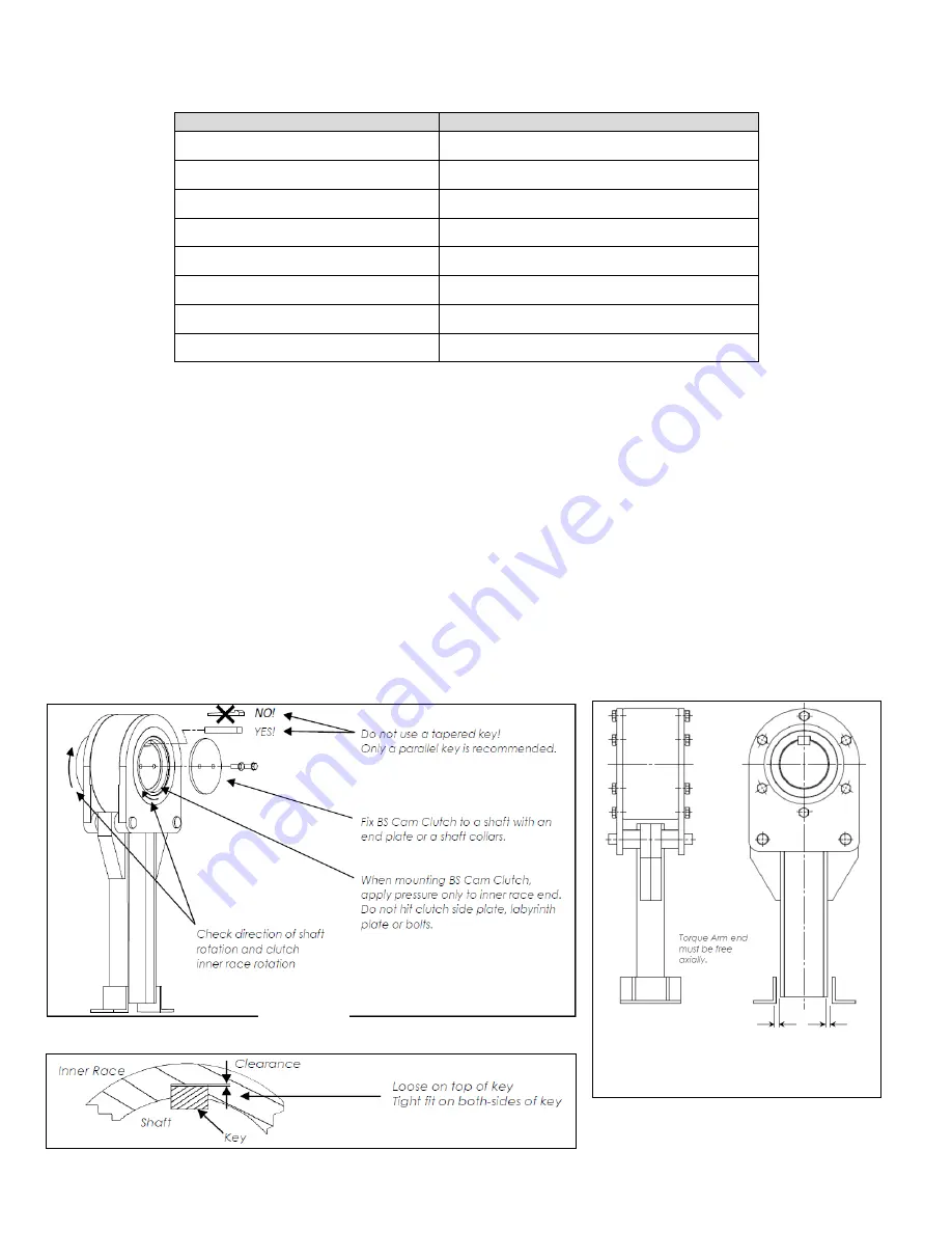
2.  Before installation, verify that the rotation of inner race is in the same direction as the direction of the conveyor shaft. 


3.  Clean the shaft and remove burrs. 


4.  Only a parallel key  is recommended for Backstop fixing. Do not use a tapered key. And there must be clearance between 

Backstop keyway and key top. The key should be in accordance with ANSI B17, 1-1967 (R 1998). See Fig 1 and 2. 


5.  Apply pressure only on the end face of inner race when installing the Backstop onto the shaft. Do not hit the side plate, labyrinth 

plate or bolts with a hammer. See Fig 1. 
 

6.  Lift torque arm and attach it to the Backstop with torque arm pins and cotter pins with Backstop. Coat pins with grease for easy 

mounting of the Backstop and preventing stuck pins. 


7.  The end of torque arm will move to some extent while the conveyor is operating. Support the torque arm end only in the direction 

of rotation, be sure to allow it a certain amount of free movement axially. See Fig 3. The Backstop sustains damage if the torque 
arm end tip is fixed securely. 
 

8.  In order to suppress the temperature rise of Backstop and to extend the lubricant life, installation of a protective cover against 

direct sunshine is recommended. 


Fig 3 


Total clearance should 
be between 0.1 to 0.2 
i

h  

Fig 1 


Fig 2 

Summary of Contents for BS115F

Page 1: ...uipment or other applicable safety standards When revisions of these standards are published the updated edition shall apply 2 Always lock out the power switch before installing removing lubricating o...

Page 2: ...haft 3 Clean the shaft and remove burrs 4 Only a parallel key is recommended for Backstop fixing Do not use a tapered key And there must be clearance between Backstop keyway and key top The key should...

Page 3: ...umbling sound this is normal and of no concern If an abnormal variation in sound is heard the following points could be causes a Installation problem with torque arm b Extreme wear caused by poor lubr...

Page 4: ...0 4 Size BS225F BS250F BS270F BS300F BS360F BS425F BS465F OZ Liters 43 29 1 3 96 57 2 9 109 89 3 3 139 86 4 2 159 84 4 8 186 48 5 6 233 1 7 0 3 Cleaning process is complete when the drained oil is cl...

Page 5: ...2 Construction Inner race Thrust bearing Torque arm Labyrinth ring Outer race Side plate Pin Socket plug Cam cage Labyrinth plate Oil seal Cotter pin...

Page 6: ...1 E Marquardt Drive Wheeling IL 60090 Tel 800 323 7790 Fax 847 459 9515 http www ustsubaki com Taiwan Tsubakimoto Co http tsubakimoto com tw Tsubaki of Canada Limited 1630 Drew Road Mississauga ON L5S...

Page 7: ...ados u otros est ndares de seguridad aplicables Cuando se publiquen las modificaciones de estas normas aplicar la edici n actualizada 2 Siempre bloquee el interruptor de energ a antes de instalar remo...

Page 8: ...b...

Page 9: ...ionamiento se escucha el ruido mediante una varilla amplificadora de ruido como un sonido de baja frecuencia continuo esto es normal y no hay de qu preocuparse Si se escucha una variaci n anormal en e...

Page 10: ...os 3 33 0 1 3 33 0 1 6 66 0 2 9 99 0 3 9 99 0 3 13 32 0 4 Tama o BS225F BS250F BS270F BS300F BS360F BS425F BS465F OZ Litros 43 29 1 3 96 57 2 9 109 89 3 3 139 86 4 2 159 84 4 8 186 48 5 6 233 1 7 0 3...

Page 11: ...Construcci n Anillo interior Cojinete de empuje Brazo de torsi n Anillo laberinto Anillo exterior Placa lateral Pasador Conector macho Jaula de leva Placa laberinto Ret n de aceite Pasador de chaveta...

Page 12: ...sion LLC 301 E Marquardt Drive Wheeling IL 60090 Tel 800 323 7790 Fax 847 459 9515 http www ustsubaki com Taiwan Tsubakimoto Co http tsubakimoto com tw Tsubaki of Canada Limited 1630 Drew Road Mississ...

Page 13: ...relacionados ou outras normas de seguran a aplic veis Quando revis es dessas normas forem publicadas a edi o atualizada dever se aplicar 2 Sempre trave o interruptor antes de instalar remover lubrifi...

Page 14: ...ira na mesma dire o que o eixo do transportador 3 Limpe o eixo e remova rebarbas 4 Somente uma chave paralela recomendada para fixa o do receptor N o use uma chave c nica E deve haver um espa o entre...

Page 15: ...r do equipamento operado Verifica o de ru do Durante a opera o se for detectado um ru do por um bast o acentuador de ru do como um som de estrondo cont nuo isso normal e n o deve ser preocupante Se um...

Page 16: ...baixo Quantidade de leo de limpeza Tamanho BS85F BS95F BS115F BS140F BS165F BS200F OZ Litros 3 33 0 1 3 33 0 1 6 66 0 2 9 99 0 3 9 99 0 3 13 32 0 4 Tamanho BS225F BS250F BS270F BS300F BS360F BS425F BS...

Page 17: ...2 Constru o Anel interno Rolamento de empuxo Bra o de torque Anel tipo labirinto Anel externo Placa lateral Pino Tomada do soquete Prote o de roda Placa do tipo labirinto Selante de leo Contrapino...

Page 18: ...LLC 301 E Marquardt Drive Wheeling IL 60090 Tel 800 323 7790 Fax 847 459 9515 http www ustsubaki com Taiwan Tsubakimoto Co http tsubakimoto com tw Tsubaki of Canada Limited 1630 Drew Road Mississauga...

Reviews: