background image

Instrument Panels

BL90236,0000003 -19-19MAR14-1/1

Instrument Panel

John Deere PowerTech™ OEM engines have an electronic
control system, which has controls and gauges as shown.
The following information applies only to those controls
and gauges supplied by John Deere. Refer to your
engine application manual for specific guidelines if John
Deere-sourced controls and instrumentation are not used.

The following is a brief description of the available optional
electronic controls and gauges found on John Deere
provided instrument panels. Refer to manufacturer’s
literature for information on controls not provided by John
Deere.

Instrument Panel

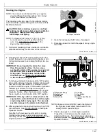
A — Diagnostic Gauge

The diagnostic gauge (A) allows the operator to view fuel
level, DEF level, engine parameters, diagnostic trouble
codes (DTCs), and other engine functions. The gauge is
linked to the electronic control system and its sensors.
This allows the operator to monitor engine functions and
to troubleshoot the engine systems when needed.

B — Arrow Keys

The arrow keys (B) allows the operator to select menu
items

C — Menu Key

The menu key (C) allow the operator to access the main
menu of the diagnostic gauge.

D — Select Key

The select key (D) allows the operator to access menu
items selected by the arrow keys (B) and confirm changes
made by the operator.

E — Exit Key

The exit key (E) allows the operator to cancel an option
and to go back to the previous menu.

F — Key Start Switch

A

B

C

D

E

F

G

H

RG23644

—UN—27AUG13

Instrument Panel

A—Diagnostic Gauge
B—Arrow Keys
C—Menu Key
D—Select Key

E—Exit Key
F— Key Switch
G—Cover
H—Speed Select Rocker

Switch

The three-position key start switch (F) controls the engine
electrical system. When the key switch is turned clockwise
to “START”, the engine will crank. When the engine starts,
the key is released and returns to the “ON” (RUN) position.

G — Cover

The cover (G) hides an expansion slot for an additional
switch.

H — Speed Select Rocker Switch

The speed select switch (H) is used to bump engine speed
up (+) or down (-) in small increments during operation.

PowerTech is a trademark of Deere & Company

15-1

032015

PN=47

Summary of Contents for PTV100/72

Page 1: ...www tse international com 5301 Shreveport Blanchard Hwy Shreveport Louisiana 71107 USA P 318 929 2368 F 318 929 4853 Owner s Manual Model PTV100 72 Puller Tensioner Serial Number 1 01 ...

Page 2: ...ctor or rope diameters Conductor or pulling line is imbedded in the elastomer lined V groove of the bullwheel TSE s unique hydraulic system allows the operator to preset the maximum pulling tension and provides infinite linespeed and linepull control The machine design incorporates a pivoting bullwheel arrangement which automatically aligns the bullwheel with the point on the reel from which the c...

Page 3: ...e to be returned prepaid to TSE Items not returned within 30 days will result in the RGA closure and may result in a denial of the claim 3 Warranty submission must be on the standard TSE International Inc claim form Claims that are not will be classified as pending until proper forms are submitted All claims must have an estimated cost associated with each item under discrepancy 4 Major subcompone...

Page 4: ...dual application of the equipment described in this manual The contents of this manual are intended as a basis of for operation maintenance and parts listing of the unit in its intended and anticipated use as it stands alone in conjunction with other equipment The Equipment described in this manual is potentially dangerous if improperly or carelessly operated For the protection of personnel and eq...

Page 5: ...s innovative products with Premium Customer Service Our comprehensive Service Department provides TSE customers with the service parts and technical assistance they need to maintain their equipment in top operating condition For Customer Service on Your Model Serial No PLEASE CALL 1 800 825 2402 Our People Care Our Equipment is the Proof PTV100 72 18 5073 01 ...

Page 6: ...der the replacement part locate the part from the drawings in this manual and give the following information 1 Unit Model No From the plates on the unit s frame 2 Unit Serial No From the plate on the unit s frame will contain numbers only 3 Part Number If available 4 Description If part no not available 5 Quantity Required On large components such as transmissions engines multiple pump drives etc ...

Page 7: ...y trained operators who are critically aware of the proper procedures operating parameters and limitations potential dangers and application of this equipment should be allowed to touch the controls at any time There is potential DANGER of ELECTRICAL SHOCK when operating this machine Ground the unit in accordance with the regulations of the using organization Various methods of bonding isolation a...

Page 8: ...which after shipment from the factory of TSE has not been altered changed repaired or treated in any manner whatsoever unless such alteration change repair or treatment has been previously authorized in writing by TSE or has been performed by the authorized service representative of TSE This Warranty to repair is the only Warranty either express implied or statutory upon which the said machinery i...

Page 9: ...THODS Grounding Equipment and Methods information is covered in the following publication IEEE GUIDE TO INSTALLATION OF OVERHEAD TRANSMISSION LINE CONDUCTORS IEEE STD 524 2003 The above publication is available through the following organization THE INSTITUTE OF ELECTRICAL AND ELECTRONICS ENGINEERS INC 3 PARK AVENUE NEW YORK NY 10016 5997 USA ...

Page 10: ...hese decals be missing they could prevent the proper operation and or maintenance of the unit which may result in personal injury or property damage If any of these decals are missing please contact us for a replacement Order the decal s by stating the decal description number and quantity TSE INTERNATIONAL 5301 SHREVEPORT BLANCHARD HWY SHREVEPORT LA 71107 ATTENTION SERVICE MANAGER TELEPHONE 800 8...

Page 11: ......

Page 12: ......

Page 13: ...E BULLWHEEL MODULE ASSEMBLY 8600890 A V GROOVE BULLWHEEL ASSEMBLY 6800003 B DRIVE ASSEMBLY BULLWHEEL 8800022 C LEVELWIND ASSEMBLY 8602374 A ENGINE PUMP ASSEMBLY FT4 8800026 B CONTROL PANEL ASSEMBLY 8602063 DRIVE ASSEMBLY REEL SHAFT 8602064 B HYDRAULIC SCHEMATIC 8602379 ELECTRICAL SCHEMATIC 7601123 A LIGHTING DIAGRAM 882003 J REEL SHAFT ASSEMBLY SECTION V VENDOR INFORMATION ENGINE PUMP DRIVE PUMP M...

Page 14: ...bilizers adjustable Pintle Eye Tow Hitch Grounding Lugs Tie Down Loops Highway Lighting and Electric Trailer Brakes CAUTION WHEN THIS SIGN APPEARS ON THESE PAGES IT INDICATES WHERE SPECIAL ATTENTION SHOULD BE PAID TO THE INSTRUCTIONS GIVEN PERSONAL INJURY OR DAMAGE TO THE EQUIPMENT MAY OCCUR IF THE INSTRUCTIONS ARE NOT FOLLOWED Specifications APPROXIMATE DIMENSIONS WITHOUT REEL Overall Length 308 ...

Page 15: ...ront 2 Rear Axle 30 000 lb Tandem Hub 8 Studs on 275mm ENGINE Horsepower 173 HP Model John Deere FT4 Fuel Diesel Fuel Reservoir Capacity 40 Gallon PERFORMANCE Maximum Linepull 11 000 lbs Continuous Linepull 10 000 lbs Line Speed 0 4 0 mph WARNING THESE VALUES ARE A MAXIMUM AND MUST NOT BE EXCEEDED ...

Page 16: ...heel are controlled with individual Levers which regulate the degree of Pump Stroke in both directions from Neutral CENTER Movement of the Direction Control Lever UP causes the Bullwheels or Reel Drive to PAYOUT and movement of the Direction Control Lever DOWN causes the Bullwheels or Reel Drive to PULL IN The Bullwheel speed is ZERO with the Direction Control Lever in the NEUTRAL position 2 PRESS...

Page 17: ...ANUAL position for desired control In the MANUAL mode use the manual Levelwind Direction Control to operate the Levelwind left and right The MANUAL mode is used primarily for Pulling In the conductor The AUTO mode is to be used only when tensioning 7 LEVELWIND DIRECTION CONTROL When operating in the MANUAL mode direction is controlled through this Joystick 8 LEVELWIND SPEED CONTROL By turning the ...

Page 18: ...PTIONAL This switch is located on the rear of the curbside fender of the unit See figure 4 It is used to engage or disengage the reel drive from the reel shaft Note before using the switch the T Lock pin must be removed from the shaft FIGURE 4 Reel Installation Perform the following procedures to install the reel a Locate the unit on level ground b Disengage the reel drive motor from the reel shaf...

Page 19: ...y hand to allow the drive to engage fully NOTE ENSURE CABLE IS UNDERWOUND ON THE REEL FACING THE BULLWHEEL NOTE FOR SMALL REELS IT MAY BE REQUIRED TO RAISE FRONT OF MACHINE CAUTION IT IS EXTREMELY IMPORTANT THAT THE REAR STABILIZERS ARE DOWN BEFORE ATTEMPTING TO LOAD A REEL FAILURE TO DO SO WILL CAUSE THE NOSE OF THE TRAILER TO LIFT EQUIPMENT DAMAGE OR PERSONAL INJURY COULD OCCUR Field Set Up Anch...

Page 20: ...al Control Lever slightly into the PULL IN position c Check reading on Bullwheel Hydraulic Gauge If starting first PULL and required Working Pressure is not known set Bullwheel Pressure to 1500 PSI 103 BARS Adjust the pressure with the Bullwheel Pressure Regulator Control Turn clockwise to raise pressure or counter clockwise to reduce pressure d Return Bullwheel Directional Control Lever to the CE...

Page 21: ...the PULL is started the Reel Drive Hydraulic Pressure Gauge will read the Preset Pressure The Bullwheel Hydraulic Pressure Gauge will read a Low Pressure at first but this pressure will increase as the Puller picks up the slack in the Pulling Line If the pressure reaches the Preset Pressure the Puller will stop moving Line It will not stop pulling but can only pull at the Preset Pressure If the Pu...

Page 22: ...nal Control Lever into the TENSION position f Release Bullwheel Brake and simultaneously move the Bullwheel Directional Control Lever into the TENSION position g Instruct the Puller operator that you are ready for him to start the Pull h As the conductor begins to move through the bullwheel regulate the line tension of the conductor by using the Bullwheel Linepull Control Clockwise adjustment will...

Page 23: ...perator that you are ready for him to start the Pull g As the conductor begins to move regulate the line tension of the conductor by using the Reelwinder Linepull Control Clockwise adjustment will increase the tension counterclockwise adjustment will decrease the tension E TOWING Before towing the unit check the following a Jacks fully retracted See Figures 2 3 b Wheel Brakes operative c Lights op...

Page 24: ... a piece of cardboard or other material as detector rather than your hand Pressurized hydraulic fluid escaping from a faulty component can penetrate the skin and cause serious injury 7 Do not change the pressure setting of any hydraulic valves unless authorized instruction has been obtained 8 Ensure that all tire and rim parts are undamaged and correctly assembled before inflating the tires 9 Use ...

Page 25: ...to highlight any occurrence of a potentially hazardous malfunction On a daily basis walk around the unit and look closely for any indication of the following 1 Loose threaded connections 2 Metal fatigue or excessive corrosion 3 Abraded hose surfaces 4 Hydraulic fluid leakage 5 Possible obstruction of moving parts especially in the drive train To ensure proper operation and long life of your TSE In...

Page 26: ...HAT HYDRAULIC FLUID IS USED IN YOUR MACHINE ISO 46 567851 HYDRAULIC SYSTEM FLUID UTILITY EP 2 GREASE MULTIPURPOSE GREASE BEARINGS SHAFTS FRICTION COMPONENTS LUBRIPLATE CHAIN CABLE FLUID PENETRATING FLUID SAE 10 ISO 32 CHAINS WIRE ROPES CABLES SPARTAN EP150 INDUSTRIAL GEAR OIL ISO 150 GEARBOXES REDUCERS SEE VENDOR LITERATURE FOR VARIATIONS AND AMOUNTS SUPER MPGO 80W90 PETROLEUM OIL BLEND PUMP DRIVE...

Page 27: ...IVOT POINTS X L CHAIN DRIVES O L LUBRICATE COUPLINGS X BOLTED CONNECTIONS X X INSPECT CORRECT HYDRAULIC PLUMBING X HYDRAULIC RESERVOIR 4 X O CLEAN LUBRICATE HYDRAULIC FILTERS 2 R 3 HYDRAULIC HOSES X F FLUSH CHANGE MISC COMPONENTS 1 L 1 Items such as engines pumps pump drives motors reducers brakes etc on your equipment should be serviced according to the manufacturer s maintenance schedule see out...

Page 28: ......

Page 29: ......

Page 30: ......

Page 31: ......

Page 32: ......

Page 33: ......

Page 34: ......

Page 35: ......

Page 36: ......

Page 37: ......

Page 38: ......

Page 39: ......

Page 40: ......

Page 41: ......

Page 42: ......

Page 43: ...ts are known to the State of California to cause cancer birth defects and other reproductive harm If this product contains a gasoline engine WARNING The engine exhaust from this product contains chemicals known to the State of California to cause cancer birth defects or other reproductive harm The State of California requires the above two warnings Additional Proposition 65 Warnings can be found i...

Page 44: ......

Page 45: ...m warranty Equipment operators can t afford downtime or unexpected repairs That s why we offer a 2 year 2 000 hour warranty with unlimited hours in the first year on our OEM industrial and marine engines This warranty takes effect the date that the engine is delivered to the first retail purchaser In addition extended warranties are available under certain conditions John Deere offers a variety of...

Page 46: ...in loss of warranty protection for this engine CERTAIN ENGINE ACCESSORIES such as radiator air cleaner and instruments are optional equipment on John Deere OEM Engines These accessories may be provided by the equipment manufacturer instead of John Deere This operator s manual applies only to the engine and those options available through the John Deere distribution network NOTE This operator s man...

Page 47: ...Introduction Continued on next page ZE59858 0000007 19 11MAR14 1 2 Identification Views RG25233 UN 10MAR14 4045HFC09 Left View RG25234 UN 10MAR14 4045HFC09 Right View 032015 PN 5 ...

Page 48: ...Introduction ZE59858 0000007 19 11MAR14 2 2 RG25231 UN 10MAR14 4045HFC04 Left View RG25232 UN 10MAR14 4045HFC04 Right View 032015 PN 6 ...

Page 49: ...Hy Gard Hy Gard is a trademark of Deere Company JDLink JDLink is a trademark of Deere Company JDParts JDParts is a trademark of Deere Company John Deere John Deere is a trademark of Deere Company Loctite Loctite is a trademark of Henkel Corporation Metri Pack Metri Pack is a trademark of Delphi Connection Systems OILSCAN PLUS OILSCAN PLUS is a trademark of Deere Company Oilscan Oilscan is a tradem...

Page 50: ...n ZE59858 0000006 19 13FEB14 2 2 Vari Cool Vari Cool is a trademark of Deere Company WEATHER PACK WEATHER PACK is a trademark of Packard Electric WINDOWS WINDOWS is a trademark of Microsoft Corporation 032015 PN 8 ...

Page 51: ...uipped Engines 10 1 Storing Diesel Exhaust Fluid DEF 10 1 Refilling Diesel Exhaust Fluid DEF Tank 10 2 Testing Diesel Exhaust Fluid DEF 10 3 Disposal of Diesel Exhaust Fluid DEF 10 3 Diesel Fuel 10 4 Supplemental Diesel Fuel Additives 10 4 Lubricity of Diesel Fuel 10 5 Handling and Storing Diesel Fuel 10 5 BioDiesel Fuel 10 6 Testing Diesel Fuel 10 7 Fuel Filters 10 7 Minimizing the Effect of Cold...

Page 52: ...ar 40 7 Checking Tensioner Spring Tension 40 8 Checking Cooling System 40 8 Pressure Testing Cooling System 40 9 Page Checking and Adjusting Engine Speeds 40 10 Checking Engine Mounts 40 10 Checking Engine Ground Connection 40 10 Lubrication Maintenance 1500 Hours Changing Open Crankcase Ventilation OCV Filter 45 1 Lubrication Maintenance 3000 Hours 36 Months Checking Crankshaft Vibration Damper 5...

Page 53: ...ications 80 3 Engine Crankcase Oil Fill Quantities 80 4 Unified Inch Bolt and Screw Torque Values 80 4 Metric Bolt and Screw Torque Values 80 5 Lubrication and Maintenance Records Using Lubrication and Maintenance Records 85 1 Daily Prestarting Service 85 1 500 Hours of Operation or Every 12 Months Service 85 1 1500 Hours of Operation Service 85 2 3000 Hours of Operation or Every 36 Months Service...

Page 54: ...Contents iv 032015 PN 4 ...

Page 55: ... plate in the spaces provided below 3 This information is very important for repair parts or warranty information Engine Serial Number A Engine Model Number B NOTE On engine serial number A the seventh digit shows the emission level as follows L for Tier 3 Stage IIIA engines R for Interim Tier 4 Stage IIIB engines U for Final Tier 4 Stage IV JOHN DEERE Engine Serial Number PE4045U123456 4045HFC09 ...

Page 56: ...he first two digits of the code numbers For future reference such as ordering repair parts it is important to have these code numbers available To ensure this availability enter the third and fourth digits shown on your engine option code label in the spaces provided below Record engine base code A below as seen on your serial number plate Engine Option Codes Continued NOTE Your engine option code...

Page 57: ... Thermostat Housing 81 Primary Fuel Filter and Water Separator 40 Oil Dipstick 83 Electronic Software Vehicle Option 41 Belt Driven Front Auxiliary Drive 84 Electrical Wiring Harness 42 DEF Line 86 Fan Pulley 43 Starting Aid 87 Belt Tensioner 44 Timing Gear Cover with Gears 89 Exhaust Gas Recirculating EGR System 45 Balancer Shaft 90 Trim Options 46 Cylinder Block and Camshaft 91 Instrument Panel ...

Page 58: ...art Number SCR Serial Number A Diesel Particulate Filter Part Number B Diesel Particulate Filter Serial Number C Diesel Oxidation Catalyst Part Number D Diesel Oxidation Catalyst Serial Number E Selective Catalyst Reduction Part Number F Selective Catalyst Reduction Serial Number RG20010 UN 11FEB11 RG24024 UN 05AUG13 Serial Number Plates for Aftertreatment Record High Pressure Fuel Pump Model Numb...

Page 59: ...19 12AUG14 1 1 Record ECU Serial Number Record the part number and serial number information found on the serial number label on the Engine Control Unit ECU Part No Serial No A Serial Number Label RG26249 UN 30JUL14 01 5 032015 PN 17 ...

Page 60: ...ssages in this manual TS187 19 30SEP88 Recognize Safety Information This is a safety alert symbol When you see this symbol on your machine or in this manual be alert to the potential for personal injury Follow recommended precautions and safe operating practices T81389 UN 28JUN13 Replace Safety Signs Replace missing or damaged safety signs Use this operator s manual for correct safety sign placeme...

Page 61: ...haust some of its constituents along with certain machine components contain or emit chemicals known to the State of California to cause cancer and birth defects or other reproductive harm In addition certain fluids contained in the machine and certain products of component wear contain or emit chemicals known to the State of California to cause cancer and birth defects or other reproductive harm ...

Page 62: ...efrigerants escaping into the air can damage the Earth s atmosphere Government regulations may require a certified air conditioning service center to recover and recycle used air conditioning refrigerants Inquire on the proper way to recycle or dispose of waste from your local environmental or recycling center or from your John Deere dealer TS1133 UN 15APR13 Prevent Machine Runaway Avoid possible ...

Page 63: ... work Keep all parts in good condition and properly installed Fix damage immediately Replace worn or broken parts Remove any buildup of grease oil or debris On self propelled equipment disconnect battery ground cable before making adjustments on electrical systems or welding on machine On towed implements disconnect wiring harnesses from tractor before servicing electrical system components or wel...

Page 64: ...n you work near machine tools or moving parts If these items were to get caught severe injury could result Remove rings and other jewelry to prevent electrical shorts and entanglement in moving parts TS228 UN 23AUG88 Use Proper Tools Use tools appropriate to the work Makeshift tools and procedures can create safety hazards Use power tools only to loosen threaded parts and fasteners For loosening a...

Page 65: ...s supported solely by a jack Follow recommended procedures in this manual When implements or attachments are used with a machine always follow safety precautions listed in the implement or attachment operator s manual TS229 UN 23AUG88 Use Proper Lifting Equipment Lifting heavy components incorrectly can cause severe injury or machine damage Follow recommended procedure for removal and installation...

Page 66: ...s in place at all times during engine operation Wear close fitting clothes Stop the engine and be sure fans belts pulleys and drives are stopped before making adjustments connections or cleaning near fans and their drive components TS677 UN 21SEP89 Stay Clear of Rotating Drivelines Entanglement in rotating driveline can cause serious injury or death Keep all shields in place at all times Make sure...

Page 67: ... Slowly loosen cap to first stop to relieve pressure before removing completely TS281 UN 15APR13 Remove Paint Before Welding or Heating Avoid potentially toxic fumes and dust Hazardous fumes can be generated when paint is heated by welding soldering or using a torch Remove paint before heating Remove paint a minimum of 100 mm 4 in from area to be affected by heating If paint cannot be removed wear...

Page 68: ...ing serious injury Avoid the hazard by relieving pressure before disconnecting hydraulic or other lines Tighten all connections before applying pressure Search for leaks with a piece of cardboard Protect hands and body from high pressure fluids If an accident occurs see a doctor immediately Any fluid injected into the skin must be surgically removed within a few hours or gangrene may result Doctor...

Page 69: ... your fuel or fuel system supplier to ensure that the delivery system is in compliance with fueling standards for proper grounding and bonding practices RG22142 UN 17MAR14 RG21992 UN 21AUG13 Handle Fuel Safely Avoid Fires Handle fuel with care it is highly flammable Do not refuel the machine while smoking or when near open flame or sparks Always stop engine before refueling machine Fill fuel tank ...

Page 70: ... Handle Starting Fluid Safely Starting fluid is highly flammable Keep all sparks and flame away when using it Keep starting fluid away from batteries and cables To prevent accidental discharge when storing the pressurized can keep the cap on the container and store in a cool protected location Do not incinerate or puncture a starting fluid container Do not use starting fluid on an engine equipped ...

Page 71: ...ubber gloves Avoiding use of air pressure to clean batteries Avoiding breathing fumes when electrolyte is added Avoiding spilling or dripping electrolyte Using correct battery booster or charger procedure If acid is spilled on skin or in eyes 1 Flush skin with water 2 Apply baking soda or lime to help neutralize the acid 3 Flush eyes with water for 15 30 minutes Get medical attention immediately I...

Page 72: ...d on yourself 1 Flush your skin with water 2 Apply baking soda or lime to help neutralize the acid 3 Flush your eyes with water for 15 30 minutes Get medical attention immediately If acid is swallowed 1 Do not induce vomiting 2 Drink large amounts of water or milk but do not exceed 2 L 2 quarts 3 Get medical attention immediately TS203 UN 23AUG88 Prevent Battery Explosions Keep sparks lighted matc...

Page 73: ...LIVE 19 25SEP92 1 1 Live With Safety Before returning machine to customer make sure machine is functioning properly especially the safety systems Install all guards and shields TS231 19 07OCT88 05 14 032015 PN 31 ...

Page 74: ...y component of the aftertreatment system Do not use DEF that does not meet the required specifications or operate the engine with no DEF Never attempt to create DEF by mixing agricultural grade urea with water Agricultural grade urea does not meet the necessary specifications and can damage the aftertreatment system Do not add any chemicals or additives to DEF in an effort to prevent freezing Any ...

Page 75: ...DEF tank Ensure that the DEF tank cap area is free of debris before removing the cap Seal containers of DEF between use to prevent contamination and evaporation Avoid splashing DEF and do not allow DEF to come into contact with skin eyes or mouth DEF is not harmful to handle but DEF can be corrosive to materials such as steel iron zinc nickel copper TS1731 UN 23AUG13 aluminum and magnesium Use sui...

Page 76: ... if there is suspicion the engine or packaged DEF fluid has been contaminated with water Two approved tools are available through your John Deere dealer JDG11594 Digital DEF Refractometer A digital tool providing an easy to read concentration measurement JDG11684 DEF Refractometer Low cost alternative tool providing an analog reading Follow instructions included with either tool to obtain the meas...

Page 77: ...hange interval BEFORE using diesel fuel with sulfur content greater than 2000 mg kg 2000 ppm contact your John Deere dealer Sulfur Content for Tier 2 and Stage II Engines Use of diesel fuel with sulfur content less than 2000 mg kg 2000 ppm is RECOMMENDED Use of diesel fuel with sulfur content 2000 5000 mg kg 2000 5000 ppm REDUCES the oil and filter change interval BEFORE using diesel fuel with sul...

Page 78: ...eater than B20 Handling and Storing Diesel Fuel CAUTION Reduce the risk of fire Handle fuel carefully DO NOT fill the fuel tank when engine is running DO NOT smoke while you fill the fuel tank or service the fuel system Fill the fuel tank at the end of each day s operation to prevent water condensation and freezing during cold weather Keep all storage tanks as full as practicable to minimize conde...

Page 79: ...etergent and dispersant additives are required when using BioDiesel blends from B10 B20 and are recommended when using lower BioDiesel blends BioDiesel Use Requirements and Recommendations The petroleum diesel portion of all BioDiesel blends must meet the requirements of ASTM D975 US or EN 590 EU commercial standard BioDiesel users in the U S are strongly encouraged to purchase BioDiesel blends fr...

Page 80: ...esel fuel The fuel analysis can provide critical data such as cetane number fuel type sulfur content water content appearance suitability for cold weather operations bacteria cloud point acid number particulate contamination and whether the fuel meets specification Contact your John Deere dealer for more information on diesel fuel analysis Fuel Filters The importance of fuel filtration cannot be o...

Page 81: ...n this section Diesel Fuel Flow Additive Use John Deere Fuel Protect Diesel Fuel Conditioner winter formula which contains anti gel chemistry or equivalent fuel conditioner to treat non winter grade fuel No 2 D in North America during the cold weather season This generally extends operability to about 10 C 18 F below the fuel cloud point For operability at even lower temperatures use winter grade ...

Page 82: ...s at all emission certification levels After the break in period use John Deere Plus 50 II or other diesel engine oil as recommended in this manual Break In Plus is a trademark of Deere Company Plus 50 is a trademark of Deere Company Diesel Engine Oil Interim Tier 4 Final Tier 4 Stage IIIB and Stage IV Use oil viscosity based on the expected air temperature range during the period between oil chan...

Page 83: ... and filter service intervals Use of diesel fuel with sulfur content less than 15 mg kg 15 ppm is REQUIRED IMPORTANT To avoid engine damage Reduce oil and filter service intervals by 50 when using BioDiesel blends greater than B20 Oil analysis may allow longer service interval Use only approved oil types Approved Oil Types John Deere Plus 50 II Other Oils include API CJ 4 ACEA E9 and ACEA E6 NOTE ...

Page 84: ...following conditions are met Engine equipped with an extended drain interval oil pan Use of diesel fuel with sulfur content less than 0 0015 15 ppm 15 mg kg maximum limit Use of John Deere Plus 50 II oil Use of an approved John Deere oil filter Oil Pan Option Codes Power Rating Fuel Sulfur Content 1903 19BB 19AE 19BC 1923 19BA 1976 19AZ 19GK kW hp Other Oils John Deere Plus 50 II Other Oils John D...

Page 85: ...bricants are used Use clean containers to handle all lubricants Store lubricants and containers in an area protected from dust moisture and other contamination Store containers on their side to avoid water and dirt accumulation Make certain that all containers are properly marked to identify their contents Properly dispose of all old containers and any residual lubricant they may contain Oil Filte...

Page 86: ...olant meeting ASTM D6210 requirements Coolant concentrate meeting ASTM D6210 requirements in a 40 60 mixture of concentrate with quality water If coolant meeting one of these specifications is unavailable use a coolant concentrate or pre mix coolant that has a minimum of the following chemical and physical properties Provides cylinder liner cavitation protection according to either the John Deere ...

Page 87: ...gher concentrations of total dissolved solids Freeze Protection The relative concentrations of glycol and water in the engine coolant determine its freeze protection limit Ethylene Glycol Freeze Protection Limit 40 24 C 12 F 50 37 C 34 F 60 52 C 62 F Propylene Glycol Freeze Protection Limit 40 21 C 6 F 50 33 C 27 F 60 49 C 56 F DO NOT use a coolant water mixture greater than 60 ethylene glycol or ...

Page 88: ...e refractometer place one drop of coolant on the window and close the lid 5 Look through the eyepiece and focus as necessary 6 Record the listed freeze point for the type of coolant ethylene glycol coolant or propylene glycol being tested TS1732 UN 04SEP13 SERVICEGARD Part Number 75240 TS1733 UN 04SEP13 Image with a Drop of 50 50 Coolant Placed on the Refractometer Window SERVICEGARD is a trademar...

Page 89: ...nd to troubleshoot the engine systems when needed B Arrow Keys The arrow keys B allows the operator to select menu items C Menu Key The menu key C allow the operator to access the main menu of the diagnostic gauge D Select Key The select key D allows the operator to access menu items selected by the arrow keys B and confirm changes made by the operator E Exit Key The exit key E allows the operator...

Page 90: ...lly change from up and down to left and right depending on the menu item to be selected The menu key C allows the operator to access the main menu of the diagnostic gauge For more information see Diagnostic Gauge Main Menu The select key D allows the operator to access menu items selected by the arrow keys B and confirm changes made by the operator The exit key E allows the operator to cancel an o...

Page 91: ...t Key F Display Auto features Manual features Clock start Temperature start In Service Data list screens Engine hours Data logger Service reminders Harness diagnostics Component identification Emission system override if equipped In Utilities System settings Pressure governing ECU software update Advanced settings password protected John Deere PowerSight John Deere PowerSight is a web based servic...

Page 92: ... 500 Hours 12 Months Section Fill crankcase with seasonal viscosity grade oil See Diesel Engine Oil Interim Tier 4 Final Tier 4 Stage IIIB and Stage IV in the Fuels Lubricants and Coolants Section NOTE Some increase in oil consumption may be expected when low viscosity oils are used Check oil levels more frequently If temperature is below 0 C 32 F it may be necessary to use cold weather starting a...

Page 93: ...not start after four attempts see Engine Troubleshooting in the Troubleshooting Section 5 Turn the key start switch clockwise to the ON position Wait until the Engine Preheater Indicator light turns off then turn the key start switch F clockwise START position to crank the engine In cold weather preheater indicator light remains on longer while engine is warmed See Cold Weather Operation in the En...

Page 94: ...kly stop engine and determine cause before resuming operation Operate the engine under a lighter load and at slower than normal speed for first 15 minutes after start up DO NOT run engine at slow idle Stop engine immediately if there are any signs of part failure Symptoms that may be early signs of engine problems are Sudden drop in oil pressure Abnormal coolant temperatures Unusual noise or vibra...

Page 95: ...ds are required below 0 C 32 F They will enhance starting performance above these temperatures and may be needed to start applications that have high parasitic loads during cranking and or start acceleration to idle Using correct grade oil per engine and machine operators manual is critical to achieving adequate cold weather cranking speed Synthetic oils have improved flow at low temperatures Othe...

Page 96: ...peeds than normal for the first few minutes after start up Idling Engine Avoid excessive engine idling Prolonged idling may cause the engine coolant temperature to fall below its normal range This in turn causes crankcase oil dilution due to incomplete fuel combustion and permits formation of gummy deposits on valves pistons and piston rings It also promotes rapid accumulation of engine sludge and...

Page 97: ...ON Gas given off by battery is explosive Keep sparks and flames away from battery Before connecting or disconnecting a battery charger turn off charger Make last connection and first disconnection at a point away from battery Always connect NEGATIVE cable last and disconnect this cable first WARNING Battery posts terminals and related accessories contain lead and lead compounds chemicals known to ...

Page 98: ...n at front of engine power requirements of the accessory must be limited to values listed below IMPORTANT See OEM engine distributor for more information to prevent overloading the auxiliary drive Severe engine damage could result SAE Drive Continuous Power Maximum Intermittent Power Maximum A 30 kW 40 hp at 2500 rpm 37 kW 50 hp at 2500 rpm RG26299 UN 12AUG14 Auxiliary Gear Drive A Auxiliary Gear ...

Page 99: ...s the Diesel Oxidation Catalyst DOC and Diesel Particulate Filter DPF is a critical component in the engine s emissions control system which is required to meet governmental emissions regulations The Exhaust Filter captures diesel particulate matter or soot to prevent its release into the atmosphere This soot must be eliminated from the DPF to keep it functioning properly The process of eliminatin...

Page 100: ...it into specialized equipment Do not remove ash by using water or other chemicals Removing ash by these methods may damage the material securing the DPF in its canister resulting in the loosening of the DPF element in the canister and subjecting it to damage from vibration Failure to follow the approved ash removal methods may violate U S federal state and local hazardous waste laws along with dam...

Page 101: ...ds particulates remaining in the exhaust stream Trapped particles are eventually oxidized within the DPF through a process known as regeneration or exhaust filter cleaning Under normal machine operation and with the system in AUTO mode the exhaust filter system requires minimal operator interaction To avoid unnecessary buildup of diesel particulates or soot in the exhaust filter system 1 Utilize t...

Page 102: ...ules are formed in the exhaust DEF is injected into the exhaust stream before the SCR catalyst Through a chemical reaction in the SCR NOx is converted into nitrogen and water Water vapor is a normal by product of combustion During cold weather operation at low exhaust temperatures this water vapor can condense and resemble white smoke from the exhaust This will dissipate as operating temperature i...

Page 103: ...ndicators you will see and use on the diagnostic gauge The diesel exhaust fluid indicator A engine emissions temperature indicator B exhaust filter indicator C auto cleaning disable indicator D engine emissions system malfunction indicator E and the caution indicator F provide the operator with visual notifications and aftertreatment system operations The Arrow keys G are used to scroll up or down...

Page 104: ...enable the auto exhaust filter clean function If conditions are not safe the operator should move the machine to a safe location and engage the auto exhaust filter cleaning mode Perform manual service regeneration or follow DTC procedure When the exhaust filter indicator is combined with the stop engine indicator engine performance is further reduced by the ECU because there is an aftertreatment s...

Page 105: ...ing During this process the injector will inject small amounts of fuel into the exhaust stream to assist in cleaning the exhaust filter When the exhaust filter cleaning process has completed its cycle the cleaning indicator will automatically turn off CAUTION Servicing machine or attachments during exhaust filter cleaning can result in serious personal injury Avoid exposure and skin contact with h...

Page 106: ...tions the engine will run at elevated idle and hot temperatures for approximately 20 50 minutes Exhaust gases and exhaust filter components reach temperatures hot enough to burn people ignite or melt common materials CAUTION Always park the machine in a safe location and check for adequate fuel level before beginning the exhaust filter cleaning process Any PTO driven devices if equipped should be ...

Page 107: ...up or down to DISABLE EXH FLT CLEAN 5 Press Select key to disable exhaust filter cleaning Exhaust Filter Service Required The exhaust filter cleaning procedures listed earlier in this section clean the soot from your exhaust filter The exhaust filter also traps ash deposits over time which are not removed during an exhaust filter cleaning When the exhaust filter has run several thousand hours thes...

Page 108: ...ection IMPORTANT Recommended service intervals are for normal operating conditions Perform maintenance at interval which occurs first for example either at 500 hours of operation or every 12 months Service more often if A RG22413 UN 27AUG13 Hour Meter On Instrument Panel A Hour Meter engine operated under adverse conditions Neglecting maintenance can result in failures or permanent damage to the e...

Page 109: ...ngine Ground Connection Change Open Crankcase Ventilation OCV Filterc Check Crankshaft Vibration Damper Adjust Engine Valve Clearance Test Glow Plugs for Continuity Change DEF Dosing Unit Filter Flush and Refill Cooling System Test Thermostats Drain Water From Fuel Filters When Alarm Sounds Add Coolant Clean DEF Tank Pre Start Cleaning Guide Service Air Cleaner Filter Elements Clean Diesel Particu...

Page 110: ...ne cools down and parts contract If enough coolant weeps from the engine where coolant drips from the engine this may indicate the need to replace the coolant pump seal Contact your engine distributor or servicing dealer for repairs Check fan alternator and accessory drive belts for cracks breaks or other damage Loosen water drain valve on each fuel filter all the way so that the valve opens to dr...

Page 111: ...chemicals known to the State of California to cause cancer and reproductive harm Wash hands after handling IMPORTANT Wear personal Protective Equipment while doing any type of Battery check or replacement 1 On regular batteries check electrolyte level Fill each cell to bottom of filler neck with distilled water NOTE Low maintenance or maintenance free batteries should require little additional ser...

Page 112: ...h your eyes with water for 10 15 minutes Get medical attention immediately If acid is swallowed 1 Drink large amounts of water or milk 2 Then drink milk of magnesia beaten eggs or vegetable oil 3 Get medical attention immediately In freezing weather run engine at least 30 minutes to ensure thorough mixing after adding water to battery Replacement battery ies must meet or exceed the following recom...

Page 113: ...y engine power and the oil and filter used For more information see Diesel Engine Oil and Filter Service Intervals in the Fuels Lubricants and Coolants Section OILSCAN or OILSCAN PLUS is a John Deere sampling program to help you monitor machine performance and identify potential problems before they cause serious damage OILSCAN and OILSCAN PLUS kits are available from your John Deere engine distri...

Page 114: ...tage IV in Fuels Lubricants and Coolant Section for determining correct engine oil To determine the correct oil fill quantity for your engine see Engine Crankcase Oil Fill Quantities in the Specifications Section of this manual NOTE Crankcase oil capacity may vary slightly ALWAYS fill crankcase within crosshatch marks on dipstick DO NOT overfill 10 Start engine and run to check for possible leaks ...

Page 115: ...he skin causing serious injury Relieve pressure before disconnecting fuel or other lines Tighten all connections before applying pressure Keep hands and body away from pinholes and nozzles which eject fluids under high pressure To search for leaks use a piece of cardboard or paper Do not use your hand If any fluid is injected into the skin it must be surgically removed within a few hours by a doct...

Page 116: ...ose to filter drain valve F on bottom of filter and drain all fuel from filter canister 3 Disconnect water in fuel sensor connector E 4 Remove fuel filter element C 5 Place new O ring B on filter element 6 Apply a thin film of fuel on O ring IMPORTANT Do not fill the new filter with fuel before installing This could contaminate the fuel system with unfiltered fuel 7 Install new filter and tighten ...

Page 117: ...22 UN 13AUG14 Replace Secondary Fuel Filter Element A Secondary Fuel Filter Element B Secondary Fuel Filter Header C Bleed Vent Screw D Primer Lever screw pump primer lever until fuel flows out of bleed vent screw then tighten bleed vent screw securely Checking Belt Wear NOTE While belt is loosened inspect pulleys and bearings Rotate and feel for hard turning or any unusual sounds If pulleys or be...

Page 118: ...ioner assembly as required Specification Spring Tension 18 22 N m 13 16 lb ft A Mark B Mark RG24040 UN 07AUG13 Checking Belt Tensioner Spring Tension Checking Cooling System CAUTION Explosive release of fluids from pressurized cooling system can cause serious burns Shut off engine Only remove filler cap when cool enough to touch with bare hands Slowly loosen cap to first stop to relieve pressure b...

Page 119: ...rate Test Cooling System for Leaks NOTE Engine should be warmed up to test overall cooling system for leaks 1 Allow engine to cool then carefully remove radiator cap 2 Fill radiator with coolant to the normal operating level IMPORTANT DO NOT apply excessive pressure to cooling system doing so may damage radiator and hoses 3 Connect gauge and adapter to radiator filler neck or expansion tank Pressu...

Page 120: ...urer Follow manufacturer s guidelines for mounting specifications IMPORTANT Use only Grade SAE 8 or higher grade of hardware for engine mounting 1 Check the engine mounting brackets A vibration isolators and mounting bolts on support frame and engine block for tightness Tighten as necessary 2 Inspect overall condition of vibration isolators if equipped Replace isolators as necessary if rubber has ...

Page 121: ... leaking or bulging hoses and for good clamp tension on all hose ends Expectation for minimal service interval will be at least 1500 hours or when the service indicator light comes on or as indicated by the diagnostic gauge 1 Remove cap A 2 Remove OCV filter from canister Discard old OCV filter 3 Install new OCV filter 4 Install cap A RG26250 UN 30JUL14 Changing OCV A Cap 45 1 032015 PN 79 ...

Page 122: ...h engine COLD 1 Remove rocker arm cover and crankcase ventilation tube 2 Remove plastic plug A from engine timing rotation hole B and timing pin hole C IMPORTANT Visually inspect contact surfaces of bridges and rocker arm wear pads Check all parts for excessive wear breakage or cracks Replace parts that show visible damage Rocker arms that exhibit excessive valve clearance should be inspected more...

Page 123: ...n adjusting screw with a 4 mm hex key until feeler gauge slips with a slight drag Hold the adjusting screw from turning and tighten lock nut to specifications Specification Intake Valve Clearance Rocker Arm to Valve Bridge With Engine Cold Clearance 0 46 mm 0 018 in Exhaust Valve Clearance Rocker Arm to Valve Bridge With Engine Cold Clearance 0 53 mm 0 021 in Valve Adjusting Screw Lock Nut Torque ...

Page 124: ...Check and adjust valve clearance to the same specifications on for No 2 and 4 exhaust and No 3 and 4 intake valves 8 Install rocker arm cover gasket IMPORTANT When reinstalling rocker arm cover inspect gasket for damage prior to reusing 9 Tighten cap screws to specifications in the sequence shown Specification Rocker Arm Cover Cap Screws Torque 11 N m 97 lb in 10 Install vent tube to rocker arm co...

Page 125: ...inal 1 Remove glow plug wiring harness connector C 2 Using a multimeter check resistance from terminal B to the outer body of glow plug A If resistance is more than 10 Ohms the glow plug is damaged and must be replaced 3 If needed install new glow plugs and torque to specifications Specification Glow Plug Torque 15 N m 133 lb in RG26311 UN 13AUG14 Check Glow Plug A Glow Plug B Terminal C Harness C...

Page 126: ...r components See Access DEF Dosing Unit for location information 1 Remove DEF dosing unit filter cover A 2 Remove and discard DEF dosing unit filter equalizing element B 3 Insert Black end of DEF dosing unit filter tool C into DEF dosing unit filter D until CLICK is felt or heard indicating DEF dosing unit filter tool is fully engaged NOTE A tool such as a screwdriver can be inserted into DEF dosi...

Page 127: ...e pressure cap and allow pressure to relive before completely removing cap NOTE If COOL GARD II is not used the drain interval is reduced to 2000 hours or 24 months of operation 1 Pressure test entire cooling system and pressure cap if not previously done See Pressure Testing Cooling System in the Lubrication Maintenance 500 Hours 12 Months Section 2 Slowly open the engine cooling system filler ca...

Page 128: ...eavy duty cooling system cleaner such as Restore or Restore Plus Follow manufacturer s directions on label 10 After cleaning the cooling system drain cleaner and fill with water to flush the system Run the engine about 7 minutes Stop engine remove radiator cap and drain water 11 Close all drain valves on engine and radiator 12 Perform Testing Thermostat Opening Temperature in the Lubrication Maint...

Page 129: ...ating temperature Always loosen radiator pressure cap or drain valve slowly to relieve pressure TS281 UN 15APR13 High Pressure Fluids 1 Visually inspect area around thermostat housing for leaks 2 Remove radiator pressure cap and partially drain cooling system 3 Remove three cap screws C and thermostat cover B clean and check cover for cracks or damage 4 Remove both thermostats A from the housing A...

Page 130: ...t and a thermometer in a container of water 3 Stir the water as it heats Observe opening action of thermostat and compare temperatures to specifications NOTE Due to varying tolerances of different suppliers initial opening and full open temperatures may vary slightly from specified temperatures Specification Thermostat Opening Temperature 85 C 97 C 185 F 207 F 4 Remove thermostat and observe its c...

Page 131: ...rmostat cover B and tighten thermostat cover cap screws C to specifications Specification Thermostat Cover Cap Screw Torque 73 N m 54 lb ft 4 Fill cooling system and check for leaks IMPORTANT Air must be expelled from cooling system when refilled A Thermostats B Thermostat Cover C Cap Screws 3 Used D Thermostat Housing RG20112 UN 18MAR11 RG25248 UN 12MAR14 Installing Thermostats 60 5 032015 PN 89 ...

Page 132: ...anufacturer will terminate the warranty obligation to the purchaser In addition tampering with fuel system which alters emission related equipment on engines may result in fines or other penalties per EPA regulations or other local emission laws Do not attempt to service fuel pump fuel rail or fuel injectors yourself Special training and special tools are required See your authorized servicing dea...

Page 133: ...l Filter B Drain Valve Adding Coolant CAUTION Explosive release of fluids from pressurized cooling system can cause serious burns Shut off engine Only remove filler cap when cool enough to touch with bare hands Slowly loosen cap to relieve pressure before removing completely IMPORTANT Never pour cold liquid into a hot engine as it may crack cylinder head or block DO NOT operate engine without cool...

Page 134: ...DEF should be crystal clear with a light ammonia smell If DEF appears cloudy has a colored tint or has a profound ammonia smell it is likely not within specification DEF in this condition should not be used 1 Remove drain plug if equipped and drain or siphon bad DEF from DEF tank NOTE Cleaning can take place with DEF tank installed or removed 2 Clean DEF tank with new DEF DEF must pass visual smel...

Page 135: ...sible buildup of residue that blocks airflow may degrade machine performance and requires more frequent cleaning depending on environmental conditions Inspect difficult to observe areas daily as conditions may require additional cleaning care to remove debris Check for oil and fuel leaks daily Replace or repair any sources of leaks including gaskets seals breather tubes fittings and fluid lines Ma...

Page 136: ...essary ONLY when primary element has a hole in it 5 To replace secondary element C pull filter element out gently Immediately replace secondary element with new element to prevent dust from entering air intake system 6 Install new primary filter element Apply pressure by hand at outer rim of filter IMPORTANT Do NOT use latches on cover to force filter into air cleaner Using cover to force filter w...

Page 137: ...er gasket C is in good condition If gasket is damaged or missing replace element IMPORTANT Air cleaner MUST BE DRY before storing in plastic bag If the filter is to be stored for later use place it in a plastic bag to protect it from dust and damage RW4768 UN 15DEC88 Inspecting Primary Air Filter Element A Light B Outer Screen C Gasket Air Filter Element Storage IMPORTANT Air cleaner element MUST ...

Page 138: ...be located or moved to a suitable location with adequate ventilation To the right are symbols which may be seen on the operator interface IMPORTANT The area above and surrounding the engine during a manual exhaust filter cleaning should be free of any flammable objects as temperatures can reach as high as 550 C 1022 F NOTE For more information on the operator interface icons or exhaust filter clea...

Page 139: ...d turning or any unusual sounds If pulleys or bearings need replacement see your John Deere dealer 4 Install new belt making sure that belt is correctly seated in all pulley grooves Text on belt such as John Deere or part number should be readable when standing at the front of the engine looking back toward the rear Refer to belt routing at right for your application 5 Apply tension to belt with t...

Page 140: ...to turn the key off and on again to reprime the system before starting Checking Air Compressors If Equipped Air compressors are offered as options with John Deere OEM engines to provide compressed air to operate air powered devices like vehicle air brakes Air compressors are engine driven piston types They are either air cooled or cooled with engine coolant The compressors are lubricated with engi...

Page 141: ...he following basic diagnostic thought process Know the engine and all related systems Study the problem thoroughly Relate the symptoms to your knowledge of engine and systems Diagnose the problem starting with the easiest things first Double check before beginning the disassembly Determine cause and make a thorough repair After making repairs operate the engine under normal conditions to verify th...

Page 142: ... Incorrect Message 15 Slightly High 16 Moderately High 17 Slightly Low 18 Moderately Low 19 Communication Error 31 Condition Exists SPN Code SPN Name 27 EGR Valve Position Signal 51 Air Throttle Actuator Position Signal 94 Low Pressure Fuel Pressure Signal 97 Water in fuel Signal 100 Engine Oil Pressure Signal 101 Crankcase Pressure 102 Manifold Air Pressure Signal 103 VGT Speed Signal 105 Manifol...

Page 143: ...91 EGR Valve Drive Circuit 2795 VGT Calibration Version 2797 Injector High Voltage Supply 1 2798 Injector High Voltage Supply 2 3031 DEF Tank Fluid Temp Signal 3216 DPF Outlet NOx 3226 SCR Outlet NOx 3246 DPF Outlet Temperature 3251 DPF Differential Pressure Signal 3361 DEF Dosing Injector Signal 3464 Air Throttle Actuator Drive Circuit 3509 Sensor Supply 1 Voltage 3510 Sensor Supply 2 Voltage 351...

Page 144: ...e on the Deere electronic instrument panel according to the J1939 standard as a two part code as shown on the tables on the following pages The first part is a Suspect Parameter Number SPN followed by a Failure Mode Identifier FMI code In order to determine the exact failure both parts SPN and FMI of the code are needed The SPN identifies the system or the component that has the failure for exampl...

Page 145: ...ed splices and terminals Look for broken wires damaged splices and wire to wire shorts Use good judgment if component replacement is thought to be required NOTE The engine control unit ECU is the component LEAST likely to fail Suggestions for diagnosing intermittent faults If diagnostic charts on preceding pages indicate that the problem is intermittent try to reproduce the operating conditions th...

Page 146: ...anks Slowly Low battery output voltage or discharged battery Charge or replace batteries Too high viscosity crankcase oil Drain crankcase oil and replace with correct viscosity oil Loose or corroded connections Clean and tighten connections Hard to Start or Will Not Start Engine starting under load Disengage PTO Improper starting procedure Review starting procedure Exhaust restricted Check and cor...

Page 147: ...Deere engine distributor or servicing dealer Electronic fuel system problem See your authorized John Deere engine distributor or servicing dealer Electronic Control System problem or basic engine problem See your authorized John Deere engine distributor or servicing dealer Lack of Engine Power Intake air restriction Service air cleaner Exhaust restricted Check and correct exhaust restriction Poor ...

Page 148: ... John Deere engine distributor or servicing dealer Excessive Fuel Consumption Engine overloaded Reduce engine load Air cleaner restricted or dirty Replace air cleaner element as required Compression too low Determine cause of low compression and repair as required Leaks in fuel supply system Locate source of leak and repair as required Improper type of fuel Drain fuel and replace with proper grade...

Page 149: ... pump repair replace pump as required See your authorized John Deere engine distributor or servicing dealer Abnormal Engine Noise Worn main or connecting rod bearings Determine bearing clearance See your authorized John Deere engine distributor or servicing dealer Excessive crankshaft end play Check crankshaft end play See your authorized John Deere engine distributor or servicing dealer Loose mai...

Page 150: ...Loose or worn rocker arms Inspect rocker arms for wear See your authorized John Deere engine distributor or servicing dealer Bent pushrods Inspect pushrods for straightness and check contact ends for wear and damage See your authorized John Deere engine distributor or servicing dealer Broken valve springs Inspect valve springs See your authorized John Deere engine distributor or servicing dealer B...

Page 151: ...hn Deere engine distributor or servicing dealer Air leak in engine intake or exhaust manifold Check intake and exhaust manifold gaskets and manifolds repair as required See your authorized John Deere engine distributor or servicing dealer Improper clearance between turbine wheel and turbine housing Inspect turbocharger repair replace as required See your authorized John Deere engine distributor or...

Page 152: ...ealer Improper type of fuel Drain fuel and replace with proper grade and quality of fuel for operating condition Poor fuel quality Drain fuel and replace with proper grade and quality of fuel for operating condition Low engine temperature Warm up engine to normal operating temperature Defective thermostat Remove and check thermostat Defective fuel injectors See your authorized John Deere engine di...

Page 153: ...aintenance 6000 Hours 72 Months Section Engine overloaded Reduce engine load Loose or defective fan belt Check automatic belt tensioner and belts Replace as required See Checking Tensioner Spring Tension in the Lubrication Maintenance 500 Hours 12 Months Section Defective or wrong type of thermostats Test thermostat opening temperature replace thermostats as required Damaged cylinder head gasket R...

Page 154: ... Deere engine distributor or servicing dealer Leaking oil cooler Pressure test oil cooler repair replace as required See your authorized John Deere engine distributor or servicing dealer Defective oil cooler O rings Remove and inspect oil cooler O rings replace as required See your authorized John Deere engine distributor or servicing dealer EGR cooler system leaking Pressure test EGR cooler syste...

Page 155: ...e engine distributor or servicing dealer Crankcase oil level too high Check engine oil level and drain as necessary High Oil Pressure Improper oil classification Drain crankcase and refill with correct oil Faulty pressure sensor Replace sensor See your authorized John Deere engine distributor or servicing dealer Oil pressure regulating valve failure Remove and inspect oil pressure regulating valve...

Page 156: ...easure valve stems and valve guides repair as required See your authorized John Deere engine distributor or servicing dealer Piston ring grooves excessively worn Remove and inspect pistons See your authorized John Deere engine distributor or servicing dealer Piston rings sticking in ring grooves Remove and inspect pistons See your authorized John Deere engine distributor or servicing dealer Insuff...

Page 157: ...st charging system Batteries Will Not Charge Loose or corroded connections Clean and tighten connections Sulfated or worn out batteries Replace batteries Stretched belt or defective belt tensioner Adjust belt tension or replace belts Starter and Hourmeter Functions Rest of Electrical System Does Not Function Blown fuse Replace fuse Entire Electrical System Does Not Function Faulty battery connecti...

Page 158: ...9858 0000027 19 30JUL14 1 4 Engine Wiring Harness Layout RG25766 UN 08MAY14 A Intake Air Sensor B Exhaust Manifold Pressure Sensor C Engine Coolant Temperature Sensor D Crankshaft Position Sensor E Engine Oil Pressure Sensor 70 18 032015 PN 116 ...

Page 159: ...d on next page ZE59858 0000027 19 30JUL14 2 4 RG25768 UN 08MAY14 A Exhaust Throttle Actuator B Fuel Rail Pressure Relief Valve C Fuel Rail Pressure Sensor D Suction Control Valve E Camshaft Position Sensor 70 19 032015 PN 117 ...

Page 160: ...nued on next page ZE59858 0000027 19 30JUL14 3 4 RG25769 UN 08MAY14 A EGR Valve B Charge Air Cooler Outlet Temperature Sensor C Cold Start Aid Relay D Water In Fuel WIF Sensor E Crankcase Pressure Sensor 70 20 032015 PN 118 ...

Page 161: ... 4 RG25770 UN 08MAY14 A Manifold Air Pressure Sensor B Fuel Injector Harness Connector C EGR Temperature Sensor D EGR Flow Sensor E Fuel Temperature Sensor F Low Pressure Fuel Pressure Sensor G Manifold Air Temperature Sensor 70 21 032015 PN 119 ...

Page 162: ...r flammable material from area before welding Allow fumes to disperse at least 15 minutes before welding or heating IMPORTANT Welding on the engine is NOT ALLOWED If welding must be performed on the machine follow these precautions IMPORTANT High currents or electrostatic discharge into electronic components from welding may cause permanent damage 1 Remove paint from the area to be welded and grou...

Page 163: ...04 03 6 5499 5498 5493 5495 5491 5496 5499 5 5498 4 5493 3 5495 8 5491 7 5496 6 5499 02 1 5 2 6 3 7 4 8 1 5 2 6 3 7 4 8 1 8 4 CYL 1 CYL 2 CYL 3 CYL 4 7 6 7 5 8 3 23 5410 2 3 4 To Diagram 5 A 14 5817 22 5003 Y5004 Electric Low Pressure Fuel Pump If Equipped 2 5003 1 5817 1 2 1 2 49 5826 24 50 5821 5658 39 5469 B5107 Low Pressure Fuel Pressure Sensor 3 5469 2 5658 1 5821 1 2 3 1 2 3 B5209 Fuel Tempe...

Page 164: ...r Supply 6b Positive A5501 33 5498 Gray Injector 3 Pulse A5501 39 5469 White Low Pressure Fuel Pressure Sensor Signal A5501 43 5495 Green Injector 4 Pulse A5501 44 5493 Orange Injector 1 Pulse A5501 48 5427 Violet Fuel Temperature Sensor Signal A5501 49 5826 Blue Sensor Return 10 A5501 50 5658 Gray Sensor Return 6 B To 4 5 L Wiring Diagram 5 or 4 5 L Wiring Diagram 7 B5107 Low Pressure Fuel Pressu...

Page 165: ... 3 5509 2 5633 6 5016 4 5018 1 5631 1 2 3 4 5 6 1 2 3 4 5 6 B5102 Exhaust Manifold Pressure Sensor 3 5465 2 5614 11 5465 1 5626 4 5423 3 5425 07 6 5421 08 52 2 5614 1 5626 5423 5425 5421 5614 5626 25 27 Y5400 EGR Valve 1 2 3 4 5 6 1 2 3 4 5 6 1 2 3 1 2 3 3 5646 2 5429 54 5429 1 5671 3 5646 1 2 5671 5429 3 5429 5 5332 5082 1 2 5643 5671 32 5671 21 5646 R5604 Cold Start Aid Interconnect K5803 Cold S...

Page 166: ...sure Sensor Signal A5501 27 5626 Blue 5 V Sensor Supply 6a Positive A5501 32 5671 Brown Cold Start Aid Drive Positive A5501 36 5509 White Exhaust Throttle Actuator Position Signal A5501 41 5633 Orange 5 V Sensor Supply 3 Return A5501 52 5425 Green EGR Valve Position Sensor Signal A5501 54 5429 White Cold Start Aid Signal C 5082 Red Battery Power Positive To 4 5 L Wiring Diagram 10 B5101 Engine Oil...

Page 167: ... 5623 1 3 2 18 5053 45 5621 1 1 2 2 3 3 To Diagram 5 or 7 D RG26329 UN 18AUG14 A5502 ECU Harness Connector 2 A5502 09 5456 Blue Manifold Air Temperature Sensor Signal A5502 14 5628 Gray Sensor Return 2 A5502 15 5623 Orange 5 V Sensor Supply 2 Return A5502 17 5125 Green Engine Coolant Level Alarm Switch Signal A5502 18 5053 Orange Crankcase Pressure Sensor Signal A5502 23 5126 Blue Sensor Return 7 ...

Page 168: ...24 5 5015 4 5818 53 5015 47 5818 Y5005 Variable Speed Fan B5303 Fan Speed Sensor Y5014 Fan Solenoid A5501 ECU Harness Connector 1 1 2 3 4 5 6 7 8 9 10 11 12 13 14 15 16 17 23 24 25 26 27 33 34 35 36 37 43 44 45 46 47 48 49 50 51 52 53 54 18 19 20 21 22 28 29 30 31 32 38 39 40 41 42 A5502 ECU Harness Connector 2 1 2 3 4 5 6 7 8 9 10 11 12 13 14 15 16 17 23 24 25 26 27 33 34 35 36 37 43 44 45 46 47 ...

Page 169: ...ply 7 Return A5502 27 5463 Orange EGR Temperature Sensor Signal A5502 32 5023 Orange Variable Speed Fan Drive Positive A5502 33 5647 Violet Variable Speed Fan Drive Negative A5502 36 5624 Yellow 5 V Sensor Supply 7 Positive A5502 37 5468 Gray Manifold Air Pressure Sensor Signal B5103 EGR Flow Sensor B5104 Manifold Air Pressure Sensor B5207 EGR Temperature Sensor B5303 Fan Speed Sensor E To 4 5 L W...

Page 170: ...9 5 5445 6 5410 1 2 3 4 5 6 7 8 9 10 11 12 1 2 3 4 5 6 7 8 9 10 11 12 B5302 Camshaft Position Sensor 2 5445 1 5443 1 2 1 2 1 2 1 2 Y5024 Fuel Rail Pressure Relief Valve Y5002 Suction Control Valve 2 5767 1 5756 2 5419 1 5424 1 2 2 1 B5113 Fuel Rail Pressure Sensor 3 5613 2 5415 1 5611 2 3 1 2 1 3 B5301 Crankshaft Position Sensor 2 5447 1 5448 1 2 1 2 To Diagram 9 From Diagram 1 G A B5208 Engine Co...

Page 171: ...01 38 5447 Violet Crankshaft Position Sensor Signal A5501 40 5419 White Suction Control Valve Drive Negative A5501 42 5424 Yellow Suction Control Valve Drive Positive A5501 45 5804 Yellow Engine CAN High A5501 46 5805 Green Engine CAN Low A5501 51 5415 Green Fuel Rail Pressure Sensor Signal B 5826 Blue Sensor Return 10 From 4 5 L Wiring Diagram 1 B5208 Engine Coolant Temperature Sensor B5113 Fuel ...

Page 172: ...5 4 5443 7 5613 1 5030 3 5447 2 5448 10 5756 11 5767 9 5415 8 5611 5445 5443 5613 5030 5756 5767 30 38 5447 5448 5415 5611 9 5415 7 5613 8 5611 10 5756 11 5767 3 5447 4 5443 1 5030 2 5448 5 5445 1 2 3 4 5 6 7 8 9 10 11 12 1 2 3 4 5 6 7 8 9 10 11 12 B5302 Camshaft Position Sensor 2 5445 1 5443 1 2 1 2 1 2 1 2 Y5024 Fuel Rail Pressure Relief Valve 2 5767 1 5756 B5113 Fuel Rail Pressure Sensor 3 5613...

Page 173: ...8 Gray Crankshaft Position Sensor Return A5501 34 5767 Violet Fuel Rail Pressure Relief Valve Drive Negative A5501 35 5030 Black Wiring Shield A5501 37 5611 Brown 5 V Sensor Supply 1 Positive A5501 38 5447 Violet Crankshaft Position Sensor Signal A5501 51 5415 Green Fuel Rail Pressure Sensor Signal B5113 Fuel Rail Pressure Sensor B5301 Crankshaft Position Sensor B5302 Camshaft Position Sensor G To...

Page 174: ... Diagram 1 B To Diagram 9 F 1 5 2 6 3 7 4 1 2 3 4 8 5 6 7 8 Wiring Diagram For Dual Turbocharged Engines With A Low Mount Fixed Turbocharger AA RG26333 UN 21AUG14 AA Wiring Diagram For Dual Turbocharged Engines With A Low Mount Fixed Turbocharger A5501 ECU Harness Connector 1 A5501 16 5461 Brown Engine Coolant Temperature Sensor Signal A5501 40 5419 White Suction Control Valve Drive Negative A5501...

Page 175: ...Troubleshooting 70 35 032015 PN 133 ...

Page 176: ...12 1 2 3 4 5 6 1 2 E5603 DEF Dosing Unit Return Line Heater 1 2 E5601 DEF Dosing Unit Pressure Line Heater 1 2 E5602 DEF Dosing Unit Supply Line Heater 1 2 3 4 5 6 B5501 DEF Dosing Unit X5037 DEF Dosing Unit Interconnect A5502 ECU Harness Connector 2 1 2 3 4 5 6 7 8 9 10 11 12 13 14 15 16 17 23 24 25 26 27 33 34 35 36 37 43 44 45 46 47 48 49 50 51 52 53 54 18 19 20 21 22 28 29 30 31 32 38 39 40 41...

Page 177: ...ative A5502 41 5318 Gray DEF Dosing Unit Return Line Heater Negative A5502 42 5315 Green DEF Dosing Unit Supply Line Heater Negative A5502 43 5146 Blue Sensor Return 13 A5502 46 5309 White DEF Dosing Unit Pressure Sensor Signal A5502 48 5136 Blue Sensor Return 14 A5502 49 5329 White DEF Tank Fluid Level Sensor Signal A5502 51 5324 Yellow DEF Coolant Control Valve Drive Negative A5502 52 5303 Orang...

Page 178: ... 5605 10 5030 11 5604 3 5333 4 5625 1 5602 2 5331 5 5786 6 5783 47 5634 06 1 2 3 4 5 6 7 8 9 10 11 12 1 2 3 4 5 6 7 8 9 10 11 12 2 5625 3 5785 1 5634 B5109 DPF Differential Pressure Sensor Engines Equipped With A DPF Only 2 5625 1 5634 4 5786 3 5783 1 5602 5 5605 6 5604 4 5636 B5204 Aftertreatment Temperature Module 1 2 3 1 3 4 2 4 1 2 3 4 5 6 B5503 Aftertreatment Outlet NOx Sensor 1 2 3 1 2 3 R56...

Page 179: ...reatment CAN Low A5502 47 5785 Green DPF Differential Pressure Sensor Signal A5502 50 5602 Red Switched Power B5109 DPF Differential Pressure Sensor Engines Equipped With A DPF Only B5204 Aftertreatment Temperature Module B5502 Aftertreatment Inlet NOx Sensor B5503 Aftertreatment Outlet NOx Sensor E 5625 Green 5 V Sensor Supply 7 Return From 4 5 L Wiring Diagram 4 F 5783 Orange 12 V Sensor Supply ...

Page 180: ...6 7 8 9 10 11 12 13 14 15 16 17 23 24 25 26 27 33 34 35 36 37 43 44 45 46 47 48 49 50 51 52 53 54 18 19 20 21 22 28 29 30 31 32 38 39 40 41 42 Y5017 Starter Solenoid 2 3 4 30 1 X5800 Starter Relay Coil Power X5801 Starter Relay Coil Ground K5801 Starter Relay 5422 5050 G5000 Battery 5092 5092 5002 A B 5002 5222 5022 5332 5122 5092 5002 5222 5022 5332 5122 F5004 JD Link Fuse 5082 5092 F5005 ECU Pow...

Page 181: ...F5000 Control Panel Fuse 30 A F5004 JD Link Fuse 10 A F5005 ECU Power Fuse 25 A F5006 ECU Power Fuse 25 A F5007 ECU Power Fuse 25 A F5010 Transient Voltage Protection Fuse 30 A G5000 Battery G5001 Alternator H 5002 Red Control Panel Unswitched Power To 4 5 L Wiring Diagram 11 I 5002 Red Control Panel Unswitched Power To 4 5 L Wiring Diagram 11 J 5002 Red Control Panel Unswitched Power To 4 5 L Wir...

Page 182: ...3 B 5032 A 5002 B 5032 A 5002 A B A B A X J Q E N T S O R P W K V L M U G C B H D F Q 5816 R 5981 33 03 08 P 5937 N 5648 M 5773 46 34 40 W 5473 X 5050 U 5017 T 5024 47 22 V 5815 5971 5954 5714 5012 5911 5939 5917 5941 5027 5913 5039 5816 5981 5937 5648 5773 5473 5017 5024 5815 45 31 36 20 10 25 15 39 37 06 49 41 5814 5044 5915 5439 5916 5947 5918 5616 5956 5923 5936 A H G E D F B J C A B C D E K J...

Page 183: ...pply 4 Return A5503 37 5936 Blue Cruise Resume Bump Down Switch A5503 39 5947 Violet Digital Throttle A5503 40 5773 Orange Spare Driver Positive A5503 41 5956 Blue Set Accelerator Bump Up Switch A5503 45 5815 Green AC Compressor A5503 46 5937 Violet Isochronous Governor A5503 47 5473 Orange Stop Lamp A5503 48 5714 Yellow 5 V Sensor Supply 5 Return A5503 49 5616 Blue 5 V Sensor Supply 4 Positive A5...

Page 184: ...noid Application Specific S5014 Aftertreatment Interface Switch From Diagram 11 From Diagram 10 5050 N 5002 J RG26338 UN 18AUG14 A5503 ECU Harness Connector A5503 04 5798 Gray DPF Regeneration Required Lamp A5503 05 5025 Green Exhaust Temperature High Lamp A5503 26 5029 White Starter Relay Control Negative A5503 30 5034 Yellow Starter Relay Control Positive A5503 35 5796 Blue DPF Regeneration Stat...

Page 185: ... Filter Switch P5301 Vehicle Speed S5009 External Derate Switch S5005 External Shutdown Switch S5006 Cruise Remote Switch S5008 Isochronous Droop Governor Switch S5007 Cruise Brake Switch H5000 Stop Engine Lamp U5000 PWM Throttle Alternator Feedback S5100 AC High Pressure Switch S5004 Cruise On Switch Y5016 AC Solenoid 5012 5714 5039 5050 5027 5012 5954 5050 5971 5050 5939 5012 5941 5917 5911 5937...

Page 186: ...20 C 5714 Yellow 5 V Sensor Supply 5 Return X5020 D 5971 Brown Cruise Cancel Resume Switch X5020 E 5954 Yellow Cruise On Switch X5020 F 5913 Orange Secondary Throttle X5020 G 5027 Violet Air Filter Switch X5020 H 5039 White Vehicle Speed Input X5020 J 5939 White External Derate Switch X5020 K 5941 Brown External Shutdown Switch X5020 L 5917 Violet Cruise Cancel Resume Switch X5020 M 5773 Orange Sp...

Page 187: ...Troubleshooting 70 47 032015 PN 145 ...

Page 188: ...CAN Auxiliary Connector S5000 Key Switch X5054 Remote Start Connector A5504 Diagnostic Gauge R5608 Diagnostic Gauge CAN Terminator 120 Ohm K5812 Control Panel Start Relay R5003 Digital Throttle S5012 Speed Select Switch S5010 Shutdown Override Switch S5013 Bump Enable Switch P Z Y Mating Connector Located On Diagram 11 B A 54 923 B A 464 914 918 B A 947 414 914 B A 55 C 936 955 B A 915 C 911 914 2...

Page 189: ...S5012 Speed Select Switch S5013 Bump Enable Switch X5021 Control Panel Connector X5021 B 28 White Fused Unswitched Power X5021 C 914 White 5 V Sensor Supply 4 Return X5021 D 30 White Start X5021 E 31 White Battery Negative X5021 F 32 White Primary CAN Shield X5021 G 33 White Key Switch X5021 J 36 White Accessory X5021 L 915 White Primary Throttle X5021 M 911 White 5 V Sensor Supply 4 Positive X502...

Page 190: ...or 2 Replace air cleaner 3 Draining and flushing of cooling system is not necessary if the engine is only stored for less than one year However for extended storage periods of a year or longer it is recommended that the cooling system be drained flushed and refilled Refill with appropriate coolant See Diesel Engine Coolant engine with wet sleeve cylinder liners in the Fuels Lubricants and Coolants...

Page 191: ...xhaust Fluid DEF Use in Selective Catalytic Reduction SCR Equipped Engines in the Fuels Lubricants and Coolants Section for more information 7 Perform all appropriate prestarting checks See Daily Prestarting Checks in the Lubrication Maintenance Daily Section for more information IMPORTANT DO NOT operate starter more than 30 seconds at a time Wait at least 2 minutes for starter to cool before tryi...

Page 192: ...Section See Engine Power And Speed Rating Specifications in the Specifications Section Lubrication System Crankcase Oil Fill Capacity See Engine Crankcase Oil Fill Quantities in the Specifications Section See Engine Crankcase Oil Fill Quantities in the Specifications Section Oil Pressure At Rated Speed 2400 rpm Full Load With Oil Warmed to 97 C 207 F 15W40 Oil kPa Bar psi 385 3 85 56 370 3 70 54 O...

Page 193: ...28 19 19AUG14 2 2 ITEM UNIT OF MEASURE 4045HFC09 4045HFG09 4045HFC04 4045HFG04 Maximum Air Intake Restriction kPa Bar psi 12 3 0 0 44 12 3 0 0 44 Maximum Exhaust Back Pressure kPa Bar psi 30 7 5 1 09 30 7 5 1 09 80 2 032015 PN 151 ...

Page 194: ...AVEc 7AVFc 63 84 2200 800 2400 7AVG 7AVH 63 84 2200 800 2400 Industrial Units 4045HFC09 7ASP 7AST 129 173 2400 800 2600 7ASU 7ASV 129 173 2200 800 2400 7ASWc 7ASXc 116 155 2400 800 2600 7ASY 7ASZ 116 155 2400 800 2600 7ATAc 7ATBc 116 155 2200 800 2400 7ATC 7ATD 116 155 2200 800 2400 7ATEc 7ATFc 104 140 2400 800 2600 7ATG 7ATH 104 140 2400 800 2600 7ATJc 7ATKc 104 140 2200 800 2400 7ATL 7ATM 104 14...

Page 195: ...280 425 315 540 400 7 8 190 140 240 175 190 140 240 175 490 360 615 455 690 510 870 640 1 285 210 360 265 285 210 360 265 730 540 920 680 1030 760 1300 960 1 1 8 400 300 510 375 400 300 510 375 910 670 1150 850 1450 1075 1850 1350 1 1 4 570 420 725 535 570 420 725 535 1280 945 1630 1200 2050 1500 2600 1920 1 3 8 750 550 950 700 750 550 950 700 1700 1250 2140 1580 2700 2000 3400 2500 1 1 2 990 730 ...

Page 196: ...1750 1300 2200 1625 2500 1850 3150 2325 2900 2150 3700 2730 M36 1150 850 1450 1075 2250 1650 2850 2100 3200 2350 4050 3000 3750 2770 4750 3500 Torque values listed are for general use only based on the strength of the bolt or screw DO NOT use these values if a different torque value or tightening procedure is given for a specific application For stainless steel fasteners or for nuts on U bolts see...

Page 197: ...t supplied by Deere Daily Prestarting Service NOTE See Daily Prestarting Checks in the Lubrication Maintenance Daily Section for detailed procedures Check engine oil level Check coolant level Drain water from fuel filters Check air cleaner dust unloader valve and air filter restriction indicator if equipped Perform visual walk around inspection 500 Hours of Operation or Every 12 Months Service Ser...

Page 198: ...ation OCV filter Hours Date Hours Date Hours Date Hours Date 3000 Hours of Operation or Every 36 Months Service Check crankshaft vibration damper Adjust valve clearance Testing glow plugs for continuity Hours Date Hours Date Hours Date Hours Date 4500 Hours of Operation or Every 36 Months Service Change DEF dosing unit filter Hours Date Hours Date Hours Date Hours Date 85 2 032015 PN 156 ...

Page 199: ...Date Service as Required Drain water from fuel filters when alarm sounds Add coolant Clean DEF tank Pre Start Cleaning Guide Service air cleaner Clean exhaust filter Replace fan alternator belt Check fuses Check electrical wiring and connectors Check air compressor if equipped See your John Deere dealer Check Refrigerant A C compressor if equipped See your John Deere dealer Hours Date Hours Date H...

Page 200: ...nd legal requirements and for marketing and promotional purposes Sometimes we may ask our John Deere affiliates dealers or business partners to do work for us which involves your information For complete details on your privacy rights and to obtain a copy of the John Deere Privacy Statement please visit our website at https www johndeere com Warranty Duration Unless otherwise provided in writing b...

Page 201: ...antable problems Services performed by a party other than an authorized John Deere service dealer Charges by dealers for initial start up and inspection deemed unnecessary by John Deere when an Operator s Manual is supplied with the product are followed Costs related to interpretation or translation services No Representations or Implied Warranty Where permitted by law neither John Deere nor any c...

Page 202: ... number 1 319 292 5844 or in Europe fax number 33 2 38 84 62 66 Local Warranty Requirements Warranties required by local statutes will be furnished by the seller Option Codes Engine Manufacturing Configuration When in need of engine replacement parts your authorized John Deere service dealer will need to know the corresponding Option Codes for your engine The option code label on the engine rocker...

Page 203: ... The presence of an EU number signifies that the engine has been certified with the European Union countries per Directive 97 68 EC The EPA and or CARB emissions warranties do not apply to the EU countries The emissions label has applicable US EPA and or CARB regulatory year The regulatory year determines which warranty statement is applicable to engine See EPA Non road Emissions Control Warranty ...

Page 204: ...ation whichever first occurs Where a warrantable condition exists John Deere will repair or replace as it elects any part or component with a defect in materials or workmanship that would increase the engine s emissions of any regulated pollutant within the stated warranty period at no cost to you including expenses related to diagnosing and repairing or replacing emission related parts Warranty c...

Page 205: ...Warranty DX EMISSIONS EPA 19 12DEC12 2 2 TS1721 UN 15JUL13 90 6 032015 PN 163 ...

Page 206: ...et the State s stringent anti smog standards John Deere must warrant the emission control system on your engine for the periods of time listed below provided there has been no abuse neglect or improper maintenance of your engine Your emission control system may include parts such as the fuel injection system and the air induction system Also included may be hoses belts connectors and other emissio...

Page 207: ...cheduled replacement point for the part Any warranted emissions related part not scheduled for replacement as required maintenance or scheduled only for regular inspection is warranted by John Deere for the stated warranty period OWNER S WARRANTY RESPONSIBILITIES As the off road diesel engine owner you are responsible for the performance of the required maintenance listed in your Operator s Manual...

Page 208: ...Warranty Continued on next page DX EMISSIONS CARB 19 01AUG14 3 8 RG25841 UN 19MAY14 90 9 032015 PN 166 ...

Page 209: ...Warranty Continued on next page DX EMISSIONS CARB 19 01AUG14 4 8 TS1723 UN 15JUL13 90 10 032015 PN 167 ...

Page 210: ...andards John Deere must warrant the emission control system on your engine for the periods of time listed below provided there has been no abuse neglect or improper maintenance of your engine Your emission control system may include parts such as the fuel injection system and the air induction system Also included may be hoses belts connectors and other emission related assemblies John Deere warra...

Page 211: ...cheduled replacement point for the part Any warranted emissions related part not scheduled for replacement as required maintenance or scheduled only for regular inspection is warranted by John Deere for the stated warranty period OWNER S WARRANTY RESPONSIBILITIES As the off road diesel engine owner you are responsible for the performance of the required maintenance listed in your Operator s Manual...

Page 212: ...Warranty Continued on next page DX EMISSIONS CARB 19 01AUG14 7 8 RG26035 UN 24JUN14 90 13 032015 PN 170 ...

Page 213: ...Warranty DX EMISSIONS CARB 19 01AUG14 8 8 RG26036 UN 24JUN14 90 14 032015 PN 171 ...

Page 214: ...Warranty 90 15 032015 PN 172 ...

Page 215: ...40 8 Flush 60 1 Pressure test 40 9 Refill 60 1 Page Crankshaft vibration damper Checking 50 1 D Daily prestarting checks 35 1 DEF Disposal 10 3 Dosing unit filter changing 55 1 Storing 10 1 Tank cleaning 65 3 Tank refilling 10 2 Testing 10 3 Use in SCR equipped engines 10 1 DEF dosing unit Accessing 55 1 DEF dosing unit filter Changing 55 1 DEF tank Cleaning 65 3 Diagnostic Gauge Using 15 2 Diagno...

Page 216: ...ystem overview 25 3 F Fan belt 65 8 Checking belt wear 40 7 Checking spring tension 40 8 Filter replace Oil 40 3 Filters Exhaust Ash handling and disposal 25 2 Automatic cleaning 25 7 Cleaning 25 1 65 7 Cleaning and maintenance 25 1 Disable cleaning 25 9 Page Disposal 25 2 Indicators 25 5 Manual parked cleaning 25 8 Passive regeneration natural cleaning 25 7 Service required 25 9 System overview 2...

Page 217: ... DEF tank 65 3 Cleaning the exhaust filter 65 7 Drain water from fuel filters 65 2 Inspecting primary air filter element 65 6 Pre start cleaning guide 65 4 Replacing air filter element 65 5 Replacing fan belt 65 8 Daily Prestarting checks 35 1 Service interval chart 30 2 Lubrication and maintenance records 85 1 1500 hours 85 2 3000 hours or 36 months 85 2 4500 hours or 36 months 85 2 500 hours or ...

Page 218: ...and refilling cooling system 60 1 Testing thermostat opening temperature 60 3 As required 65 1 65 2 Adding coolant 65 2 Additional service information 65 1 Air filter element storage 65 6 Bleeding fuel system 65 9 Checking air compressors 65 9 Checking electrical wiring and connections 65 9 Checking fuses 65 9 Checking refrigerant A C compressor 65 9 Cleaning DEF tank 65 3 Cleaning the exhaust fil...

Page 219: ... warranty Equipment operators can t afford downtime or unexpected repairs That s why we offer a 2 year 2 000 hour warranty with unlimited hours in the first year on our OEM industrial and marine engines This warranty takes effect the date that the engine is delivered to the first retail purchaser In addition extended warranties are available under certain conditions John Deere offers a variety of ...

Page 220: ...Engine Registration IBC 2 032015 PN 178 ...

Page 221: ...eet 10 Agriculture Earth Moving Forestry Generator Set Industrial Marine Industrial Moveable Marine Propulsion Material Handling Municipal Utility Commercial On Highway Road and Miscellaneous Construction Rail Maintenance Other Purchase s Signature PRODUCT AND EQUIPMENT INFORMATION Product Serial Number Date Delivered Amount of Use Hours Miles New or Used Use of Information All personal informatio...

Page 222: ...Engine Registration BL90236 0000029 19 19NOV13 1 1 Mail In Registration MAILING INFORMATION Return Address John Deere Power Systems P O Box 5100 Waterloo IA 50704 5100 USA IBC 4 032015 PN 180 ...

Page 223: ...Engine Registration IBC 5 032015 PN 181 ...

Page 224: ...Engine Registration IBC 6 032015 PN 182 ...

Page 225: ...SERVICE MANUAL ...

Page 226: ... Inch Gear Centers 13 Oil Capacity for 8 Inch Gear Centers 14 Oil Capacity for 9 Inch Gear Centers 14 Oil Capacity for 10 5 Inch Gear Centers 15 Oil Capacity for 11 3 Inch Gear Centers 15 PART NUMBER CHARTS 1PD06 Module Pump Drive 16 2PD06 Module Pump Drive 17 3PD06 Module Pump Drive 18 2PD08 Module Pump Drive 19 3PD08 Module Pump Drive 20 4PD08 Module Pump Drive 21 4PD09 Module Pump Drive 22 2PD1...

Page 227: ...power TORSIONAL VIBRATIONS emanating from many modern diesel engines can cause severe damage to power train components resulting in premature failure To insure the integrity of the power transmission system a torsional vibration analysis should be performed and suitable vibration dampening components utilized when indicated by the analysis Durst is not responsible for damage or failure resulting f...

Page 228: ...he model description MODEL IDENTIFICATION NOMENCLATURE FOR CLUTCH ASSEMBLIES 3PD06 3PD08 3PD10 4PD08 4PD09 4PD11 2PD06 2PD08 2PD10 1PD06 3PD06 1 29I 223 CCH CCH CCH NS 1PD06 1 32I 343 CCH LS T LL LR 4PD08 1 1 111 CCV CCH CCH CCH LS TL TR LL LR 2PD08 1 40D 343 CCH DDH RS L R 2PD06 1 32 D 3 4 3 C C H C C H L S Model Ratio I Increaser D Decreaser A SAE A B SAE B C SAE C D SAE D CLUTCH HOUSING 1 SAE 1...

Page 229: ... N23 CCH DDH RS L R 2PD06 1 32 D D 1 1 C C H C C H L S Model Ratio I Increaser D Decreaser D With Drive Plate N No Drive Plate Shaft ONLY WITH DRIVE PLATE 1 SAE 14 2 SAE 11 5 3 SAE 10 4 SAE 8 S Standard Assy N Non Standard V Vertical Inverted X Special L Dipstick on Left Side R Dipstick on Right Side N No Dipstick T LR LL LR TR LL TL H Pad Mounted Horizontally V Pad Mounted Vertically PUMP SPLINE ...

Page 230: ...ompanion 003 2 50 Dia Keyed Shaft 004 2 25 Dia Keyed Shaft 005 29T 12 24 Shaft 006 20T 10 20 Shaft 007 15T 8 16 Shaft 008 Special Shaft S Standard Assy N Non Standard V Vertical Inverted X Special L Dipstick on Left Side R Dipstick on Right Side N No Dipstick T LR LL LR TR LL TL H Pad Mounted Horizontally V Pad Mounted Vertically PUMP SPLINE ADAPTER A SAE A 9T 16 32 B SAE B 13T 16 32 BB SAE BB 15T...

Page 231: ...area lubricating the spline adapters and bearings without the need for external pumps Oil volume is critical to make this feature work and the oil level should be checked frequently PUMP PADS The Durst pump pads have been simplified and no longer contain the bearing cup Pump pads can now be removed without disrupting the internal workings and alignment of the bearings and gears inside the gear box...

Page 232: ...eaves sprockets or severely angled drive lines For over hung load applications contact Durst Engineering CLUTCH DRIVEN This unit mounts directly to the engine flywheel through an over center clutch The clutch is primarily used for disconnecting the pump drive during engine start up Each clutch includes a separate installation parts and service manual 1 The clutch is not preset at the factory and c...

Page 233: ...nd 3PD10 pump drives can be mounted normal or inverted 4PD08 4PD09 and 4PD11 pump drives can ONLY be mounted in the normal orientation Failure to mount boxes in the specified orientations will cause premature failure INSTALLATION OF HYDRAULIC PUMPS TO DURST PUMP DRIVES The pump pads on the Durst pump drives offer two or four bolt mountings which can be mounted vertically or horizontally to provide...

Page 234: ...s loose of the gear box Be careful to lift the pump pads evenly to avoid damaging the pilot To avoid oil leaks all o rings are to be replaced any time the pump pad is removed 5 To access the input shaft retaining ring remove the expansion plug Remove the retaining ring from the input drive shaft and slide the shaft out of the engine adapter side see Figure A NOTE The expansion plug must be replace...

Page 235: ...ne by hand as the bearings are a slip fit see Figure C When rotating gears keep hands and fingers clear from the gear mesh 8 With all of the gears removed drive the input seal out towards the engine adapter It is required to change the input seal any time the input gear has been removed from the housing 9 To remove the bearings from the gears use a gear puller or Arbor press see Figure D NOTE Bear...

Page 236: ...r rag wipe the housings clean 3 The gears have retaining ring grooves on the output side and a seal lip on the input side Install the gears into the housing half with the input side of the gear facing down or to where the engine adapter would be attached see Figure F Tip Apply a small coat of oil to the outside of the bearing to allow gear and bearing to slide into housing easier 4 Place approxima...

Page 237: ...ress into place 060 below flush with the gear Pressing the seal too far will create a leak or possibly block oil to the bearings see Figure H Do not use sharp objects for pressing in seals Press only on the outer edge of the seal to keep from bending or damaging the seal casing 8 To install the dipstick upright the gear box Apply Loctite 609 to the dipstick tube and insert the dipstick tube until ...

Page 238: ...It is recommended to change oil after the first 500 hours or 3 months of service which ever occurs first Thereafter and under normal operating conditions Durst recommends that the oil be changed every 1000 hours or 6 months of service 3 Stop engine before attempting to check or add oil 4 Clean around dipstick and oil fill hole before checking or adding oil 5 Drain oil while the unit is still warm ...

Page 239: ... 54 Liters 1 17 Dec 1 29 Dec 1 36 Dec 1PD06 Inverted Mounting Ratio Oil Capacity 1 67 Inc 2 18 Qts 2 06 Liters 1 57 Inc 1 48 Inc 2 31 Qts 2 18 Liters 1 40 Inc 1 32 Inc 1 25 Inc 1 18 Inc 1 1 2 31 Qts 2 18 Liters 1 18 Dec 1 25 Dec 1 32 Dec 1 40 Dec 1 48 Dec 1 57 Dec 1 67 Dec 2 43 Qts 2 30 Liters 2PD06 Vertical Mounting Ratio Oil Capacity 1 67 Inc 3 10 Qts 2 93 Liters 1 57 Inc 1 48 Inc 3 60 Qts 3 41 ...

Page 240: ... 1 34 Inc 1 23 Inc 1 1 4 38 Qts 4 14 Liters 1 23 Dec 1 34 Dec 1 40 Dec 4 00 Qts 3 78 Liters 2PD08 Vertical Mounting Ratio Oil Capacity 1 40 Inc 1 34 Inc 1 23 Inc 1 1 1 23 Dec 1 34 Dec 1 40 Dec 3PD08 Inverted Mounting Ratio Oil Capacity 1 40 Inc 3 43 Qts 3 25 Liters 1 34 Inc 1 23 Inc 1 1 3 25 Qts 3 08 Liters 1 23 Dec 1 34 Dec 1 40 Dec 3 43 Qts 3 25 Liters 9 INCH GEAR CENTERS 4PD09 Normal Mounting R...

Page 241: ...ical Mounting Ratio Oil Capacity 1 38 Inc 4 50 Qts 4 25 Liters 1 29 Inc 1 21 Inc 1 1 4 50 Qts 4 25 Liters 1 21 Dec 1 29 Dec 1 38 Dec 4 50 Qts 4 25 Liters 3PD10 Inverted Mounting Ratio Oil Capacity 1 38 Inc 6 25 Qts 5 91 Liters 1 29 Inc 1 21 Inc 1 1 5 75 Qts 5 44 Liters 1 21 Dec 1 29 Dec 1 38 Dec 5 50 Qts 5 20 Liters 11 3 INCH GEAR CENTERS 4PD11 Normal Mounting Ratio Oil Capacity 1 39 Inc 7 25 Qts ...

Page 242: ... in gear box kit but is required in all inverted installations For replacement gears with bearings assembled order gear as a kit with a K number i e To order a 012104 gear with 2 012015 bearings order as K12104 J84 DOWEL PIN 2 B OUTPUT GEAR A INPUT GEAR 012236 MAGNETIC DRAIN PLUG K38 INVERTED OIL LEVEL PLUG 012166 FITTING 4400 101 VENT 012015 BEARING 4 SEE NOTE FOR DIPSTICK OR PLUG 012042 SEAL D70...

Page 243: ...der gear as a kit with a K number i e To order a 012104 gear with 2 012015 bearings order as K12104 012236 MAGNETIC DRAIN PLUG 012059 PLUG J84 DOWEL PIN 2 012166 FITTING 4400 101 VENT SEE NOTE FOR DIPSTICK AND PLUG D70 WASHER 10 D1353 CAP SCREW 10 A INPUT GEAR 012042 SEAL 012015 BEARING 6 B OUTPUT GEAR 2 012136 INPUT HOUSING 012137 OUTPUT HOUSING Complete Gear Input Output Box P N Ratio Gear A Gea...

Page 244: ...t but are required in all inverted installations For replacement gears with bearings assembled order gear as a kit with a K number i e To order a 012105 gear with 2 012015 bearings order as K12105 D1353 CAP SCREW 12 012236 MAGNETIC DRAIN PLUG 012166 FITTING 4400 101 VENT D70 WASHER 12 J84 DOWEL PIN 2 SEE NOTE FOR DIPSTICK AND PLUG K38 INVERTED OIL LEVEL PLUG 012042 SEAL 012015 BEARING 8 A INPUT GE...

Page 245: ...ear box kit but are required in all vertical installations For replacement gears with bearings assembled order gear as a kit with a K number i e To order a 012010 gear with 2 012016 bearings order as K12010 012236 MAGNETIC DRAIN PLUG 012059 PLUG J84 DOWEL PIN 2 012166 FITTING SEE NOTE FOR DIPSTICK AND PLUG 4400 101 VENT D70 WASHER 12 D1353 CAP SCREW 12 A INPUT GEAR 012042 SEAL 012016 BEARING 6 B O...

Page 246: ...kit but are required in all inverted installations For replacement gears with bearings assembled order gear as a kit with a K number i e To order a 012010 gear with 2 012016 bearings order as K12010 SEE NOTE FOR DIPSTICK AND PLUG 012236 MAGNETIC DRAIN PLUG K38 INVERTED OIL LEVEL PLUG D70 WASHER 16 D1353 CAP SCREW 16 012166 FITTING 4400 101 VENT 012042 SEAL 012016 BEARING 6 A INPUT GEAR B OUTPUT GE...

Page 247: ...h P N 012326 expansion plug provided with dipstick For replacement gears with bearings assembled order gear as a kit with a K number i e To order a 012010 gear with 2 012016 bearings order as K12010 012236 MAGNETIC DRAIN PLUG J84 DOWEL PIN 2 D70 WASHER 16 D1353 CAP SCREW 16 SEE NOTE FOR DIPSTICK AND PLUG 012166 FITTING 4400 101 VENT 012016 BEARING 10 012042 SEAL A INPUT GEAR B OUTPUT GEAR 4 012118...

Page 248: ... is plugged with P N 012326 expansion plug provided with dipstick For replacement gears with bearings assembled order gear as a kit with a K number i e To order a 012479 gear with 2 012016 bearings order as K12479 SEE NOTE FOR DIPSTICK AND PLUG D1353 CAP SCREW 16 D70 WASHER 16 J84 DOWEL PIN 2 4400 101 VENT 012166 FITTING 012016 BEARING 10 012042 SEAL A INPUT GEAR B OUTPUT GEAR 4 012468 INPUT HOUSI...

Page 249: ... kit but are required in all vertical installations For replacement gears with bearings assembled order gear as a kit with a K number i e To order a 012052 gear with 2 012016 bearings order as K12052 012236 MAGNETIC DRAIN PLUG 012059 PLUG 012166 FITTING 4400 101 VENT D1353 CAP SCREW 16 SEE NOTE FOR DIPSTICK AND PLUG D70 WASHER 16 012016 BEARING 6 012042 SEAL A INPUT GEAR B OUTPUT GEAR 2 J84 DOWEL ...

Page 250: ...ed in gear box kit but are required in all inverted installations For replacement gears with bearings assembled order gear as a kit with a K number i e To order a 012052 gear with 2 012016 bearings order as K12052 SEE NOTE FOR DIPSTICK AND PLUG 012236 MAGNETIC DRAIN PLUG K38 INVERTED OIL LEVEL PLUG D70 WASHER 16 D1353 CAP SCREW 16 4400 101 VENT 012166 FITTING 012016 BEARING 8 012042 SEAL A INPUT G...

Page 251: ... is plugged with P N 012326 expansion plug provided with dipstick For replacement gears with bearings assembled order gear as a kit with a K number i e To order a 012053 gear with 2 012016 bearings order as K12053 012236 MAGNETIC DRAIN PLUG J84 DOWEL PIN 2 D1353 CAP SCREW 18 SEE NOTE FOR DIPSTICK AND PLUG D70 WASHER 18 012166 FITTING 4400 101 VENT 012042 SEAL 012016 BEARING 10 A INPUT GEAR B OUTPU...

Page 252: ...04 K12264 21T 21T 16 32 012261 012044 K12265 23T 23T 16 32 012262 012044 K12266 27T 27T 16 32 012263 012044 PUMP SPLINE ADAPTER PUMP PAD SPLINE ADAPTER RETAINING RINGS 1 Install the first retaining ring into the furthest snap ring groove of desired gear see Figure K Note that the SAE F spline adapter requires a different retaining ring see chart 2 Insert pump spline adapter into gear Some spline a...

Page 253: ...d nut if applicable Torque bolts according to Table 1 see page 33 Do not apply Loctite or any type of thread locking material to pump pad screws 5 The C o ring seals the hydraulic pump to the gear box For installation instructions see Installation of Hydraulic Pumps to Durst Pump Drives page 7 PUMP PAD ADAPTER INSTALLATION INSTRUCTIONS CAUTION The following chart lists all available pump pad adapt...

Page 254: ...l 012046 o ring into shaft groove 3 Insert shaft into the drive gear of the gear box until the shoulder contacts input gear 4 Install 012045 retaining ring onto shaft through the back side of the gear box 5 Apply a thin coat of Loctite 609 or equivalent to the O D of the 012043 expansion plug before installation INPUT SHAFT INSTALLATION INSTRUCTIONS The following chart lists all available input sh...

Page 255: ...271 2 For C111 Clutch 12 3 8 16 012162 K12272 2 For C110 Clutch 12 3 8 16 012163 K12611 3 For SP211 Clutch 12 3 8 16 012610 K12273 3 For C111 Clutch 12 3 8 16 012164 K12274 3 For C110 Clutch 12 3 8 16 012165 CLUTCH HOUSINGS ENGINE ADAPTERS 1 Place clutch housing or engine adapter onto pump drive gear box Be sure that clutch housing or engine adapter is positioned correctly as this will locate the ...

Page 256: ...ld not exceed 0 008 4 Apply Silver Streak 200S to the external splines and slide the input shaft of the pump drive into the drive plate hub until the engine adapter seats against the engine flywheel housing Do not use the engine adapter mounting bolts to seat the pump drive engine adapter housing to the engine flywheel housing This may reduce engine crankshaft endplay and will result in premature ...

Page 257: ...619 4265 620 D Shift Yoke 4265 634 4265 634 4265 612 4265 614 4265 614 E Shift Handle 4265 633 4265 633 4265 613 4265 613 4265 613 F Operating Shaft 4265 632 4265 632 4265 616 4265 615 4265 615 G Lock Washer 4265 631 4265 631 4265 621 4265 622 4265 622 H Lock Nut 4265 629 4265 629 4265 624 4265 623 4265 623 J Drive Shaft Key 4273 921 4273 921 4273 409 4273 132 4273 132 K Hydraulic Hose Assy 4265 6...

Page 258: ...g to Table 1 page 33 5 Position the clutch over the clutch housing and install the grease hose to the clutch assembly grease port 6 Carefully lower the clutch onto the clutch shaft and into the clutch housing Using the shift handle align the shift yoke with the mating tabs on the clutch assembly 7 With the clutch installed press in the drive shaft key 8 Place the lock washer onto the clutch shaft ...

Page 259: ... that can help properly complete a specific procedure SAE Society of Automotive Engineers This group defines standards in the automotive industry to allow for interchangeability between engine and component manufacturers Iso Lube Ports located in Terrell pump pads to provide adequate oil lubrication to the pump splines TIR Total Indicator Reading This is a measurement to determine endplay on a rot...

Page 260: ...alleged defective part for Seller s inspection and no other goods shall be returned to Seller within Seller s written consent This warranty shall not extend to goods subjected to misuse abuse neglect accident or improper installation or maintenance incorrect lubrication or goods which have been altered or repaired by anyone other than Seller or its authorized representative f THE FOREGOING WARRANT...

Page 261: ...98 Beloit WI 53512 0298 1 800 356 0775 608 365 2563 Fax 608 365 2182 www durstusa com REGAL BELOIT CORPORATION is a worldwide manufacturer of mechanical and electrical motion control products 4896D 500 06 05 BP NP P N 012530 June 2005 ...

Page 262: ...saue Axial Piston Pumps and Motors Service Manual Series 90 CONTENTS ...

Page 263: ...Authorized Service Center for details A list of all Service Centers can be found in bulletin BLN 2 40527 or in brochure SAW Ident No 698266 1 1 Use of This Manual Loss of Hydrostatic Braking Ability WARNING When Series 90 units are used in vehicular hydrostatic drive systems the loss of hydro static drive line power in any mode of opera tion e g acceleration deceleration or neu tral mode may cause...

Page 264: ...lacement Control EDC 14 2 5 4 Automotive Control AC and AC II 14 2 5 5 3 Position FNR Electric Control 14 2 6 Motor Features 15 2 6 1 Motor Loop Flushing Valve and Charge Relief Valve 15 2 6 2 Variable Motor Displacement Limiters 15 2 7 Variable Motor Controls 16 2 7 1 Hydraulic 2 Position Control 16 2 7 2 Electric 2 Position Control 16 3 Technical Specifications 17 3 1 General Specifications 17 3...

Page 265: ... 9 2 4 Charge Pump 58 9 2 5 Auxiliary Pad Installation 62 9 2 6 Filtration Options 64 9 3 Pump Controls 65 9 3 1 Cover Plate 65 9 3 2 Manual Displacement Control MDC 66 9 3 3 Solenoid Override Valve for MDC 67 9 3 4 Solenoid Override Valve for MDC with Pressure Released Brake 67 9 3 5 Hydraulic and Electric Displacement Controls 68 9 3 6 Pressure Control Pilot PCP for Electric Displacement Control...

Page 266: ...ich imparts the input energyintothehydraulicfluid Thehighpressurefluid is then ported out to provide power to a remote function The swashplate angle can be varied by the control piston Altering the swashplate angle varies the dis placement of fluid in a given revolution of the input shaft A larger angle causes greater displacement which yields greater output torque for a given input A smaller angl...

Page 267: ... Series 90 MV Cross Section 90000190 Series 90 MF Cross Section Piston Roller Bearing Output Shaft Valve Plate Loop Flushing Valve Cylinder Block Fixed Swashplate In the Fixed Displacement Motor the swashplate is fixed so any variation in motor speed and torque must be made by the input mechanism i e the pump 2 1 3 Variable Displacement Motor The Variable Displacement Motor MV operates in the same...

Page 268: ...3 The Basic Closed Circuit Themainportsofthepumpareconnectedbyhydrau lic lines to the main ports of the motor Fluid flows in either direction from the pump to the motor then back to the pump in this closed circuit Either of the hydrau lic lines can be under high pressure The position of the pump swashplate determines which line is high pressure as well as the direction of fluid flow Case Drain and...

Page 269: ...d cap axial ports or both ports on one side twin ports See the Series 90 Technical Information manuals BLN 10029 and BLN 10030 or the Series 90 Price Book BLN 2 40588 for information on available options Removing the end cap will void the warranty on a Series 90 pump or motor 2 3 2 Speed Sensors An optional speed sensor can be installed on Series 90 pumps and motors to provide unit speed informa t...

Page 270: ...arge pressure at a designated level A direct acting poppet valve relieves charge pressure when ever it surpasses a certain level This level is nomi nally set referencing case pressure at 1775 rpm This nominal setting assumes the pump is in neutral zero flow in forward or reverse charge pressure will be lower The charge relief valve setting is specified on the model code of the pump Sec 8 1 1 For r...

Page 271: ...lude a pressure limiter valve 2 4 5 Pressure Limiter and High Pressure Relief Valves Series 90 pumps are designed with a sequenced pressure limiting system and high pressure relief valves When the preset pressure is reached the pressure limiter system acts to rapidly destroke the pump so as to limit the system pressure For unusu ally rapid load application the high pressure relief valve acts to im...

Page 272: ...egral or remote mounted to filter the fluid entering the charge circuit See Sec 6 for more information Suction Filtration The suction filter is placed in the circuit between the reservoir and the inlet to the charge pump When suction filtration is used a reducer fitting is placed in the charge pressure gauge port M3 Filtration de vices of this type are provided by the user Charge Pressure Filtrati...

Page 273: ...h the pump displacement control Control supply pressure is normally ported through the pressure override valve to the displacement control valve for controlling the pump s displacement If the system demands a pressure above the override setting the POR valve will override the control by reducing the control pres sure supplied to the displacement control As the control pressure reduces the internal...

Page 274: ... control input shaft is rotated toward its maximum displacement position For adjustments see Sec 8 2 2 for repairs see 9 3 2 Solenoid Override Valve A solenoid override valve option not shown here is available for MDC This safety feature will return the swashplate to zero displacement position when acti vated The valve may be set in either a normally open ornormallyclosedmode Forrepairssee9 3 3 9 ...

Page 275: ...d so the angular position of the swashplate is proportional to the EDC input For neutral adjustment see Sec 8 2 4 for repairs see Sec 9 3 5 9 3 6 and 9 3 8 2 5 4 Automotive Control AC and AC II Automotive Control AC allows a vehicle to be driven in a manner similar to an automobile with an auto matic transmission The AC control includes a three position electric control to provide direction contro...

Page 276: ... there is a pressure differen tial in the main loop The shuttle valve is spring centered to the closed position so that no high pres sure fluid is lost from the circuit when reversing pressures For charge relief valve adjustment see Sec 8 3 1 for repairs see Sec 9 4 1 MF showing location of Loop Flushing Valve 90000248 Charge Relief Valve Loop Flushing Shuttle Valve End Cap Top of Motor 90000238 M...

Page 277: ...tions of the hydraulic two position control are preset at the factory For repairs see Sec 9 5 2 and 9 5 4 2 7 2 Electric 2 Position Control This control utilizes an electric solenoid operated three way hydraulic valve to port system pressure to either of the motor displacement control pistons The motor is normally held at its maximum displacement Energizing the solenoid will cause the motor to go ...

Page 278: ...ith fixed dis placement fixed swashplate design Type of Mounting per SAE J744 SAE flange Size B mounting pad 2 bolts SAE flange Size C mounting pad 4 bolts Cartridge flange 2 bolts for motor only Port Connections See Sec 4 2 for exact specs Main pressure ports SAE flange Code 62 Remaining ports SAE straight thread O ring boss Direction of Rotation Clockwise or counterclockwise motors are bidi rect...

Page 279: ... i t n o C m u m i x a M r a b 3 i s p 4 4 t n e t t i m r e t n I m u m i x a M t r a t S d l o C r o r a b 5 i s p 3 7 t n e t t i m r e t n I m u m i n i M t r a t S d l o C r o 0 4 C 0 4 F s u o u n i t n o C m u m i x a M 4 0 1 C 0 2 2 F t n e t t i m r e t n I m u m i x a M 5 1 1 C 0 4 2 F t n e t t i m r e t n I m u m i n i M m m 5 2 s S U S 2 4 s u o u n i t n o C m u m i n i M m m 4 6 2 s...

Page 280: ... 7 5 6 3 6 9 2 4 4 7 1 1 4 3 2 2 6 6 9 2 8 7 r e w o p r e n r o c x a M W k p h 1 1 1 9 4 1 5 5 1 8 0 2 7 8 1 1 5 2 7 3 2 8 1 3 2 9 2 2 9 3 4 5 3 5 7 4 4 2 2 0 0 3 2 8 2 8 7 3 t h g i e W e g n a l F E A S g k b l 1 1 4 2 5 1 4 3 0 2 5 4 6 2 7 5 4 3 4 7 5 4 9 9 9 3 6 8 4 4 8 9 t h g i e W r o t o M e g d i r t r a C g k b l 7 1 7 3 6 2 7 5 3 3 2 7 0 4 8 8 6 4 1 0 1 n o i s n e m i D V P 0 3 0 V P...

Page 281: ...e r u s s e r P e g u a G i s p 0 0 5 r o r a b 0 5 g n i t t i F g n i R O 8 1 6 1 9 t r o P n o i t c n u F e z i S e g u a G d e d n e m m o c e R g n i t t i F d n a 1 L 2 L e s a C e r u s s e r P e g u a G i s p 0 0 1 r o r a b 0 1 g n i t t i F g n i R O E A S 2 4 0 0 3 0 4 1 8 7 5 7 0 5 5 0 0 0 1 2 1 6 1 1 1 0 3 1 2 1 6 1 5 1 0 5 2 0 8 1 2 1 8 5 1 1 X 2 X C D E C D H e r u s s e r P e g u ...

Page 282: ...1 Top View System Pressure Port B System Pressure Gauge Port M2 System Pressure Gauge Port M1 System Pressure Port A Case Drain Port L1 Case Drain Port L2 Left Side View System Pressure Port B Charge Pump Inlet Port S Charge Inlet Pressure External Control Pressure Supply Port X3 Charge Pressure Gauge Port M3 Right Side View Speed Sensor PV with Side Port End Cap and Manual Displacement Control 90...

Page 283: ...in Port L2 Left Side View System Pressure Port B Charge Pump Inlet Port S System Pressure Port A Servo Displacement Cylinder Pressure Gauge Port M5 External Control Pressure Supply Port X3 Servo Displacement Cylinder Pressure Gauge Port M4 Charge Pressure Gauge Port M3 Case Drain Port L1 Top View PV with Side Port End Cap and Remote Pressure Filtration PV with Side Port End Cap and Integral Pressu...

Page 284: ... i S e g u a G d e d n e m m o c e R g n i t t i F d n a 1 M m e t s y S e r u s s e r P A t r o P e g u a G i s p 0 0 0 0 1 r o r a b 0 0 0 1 g n i t t i F g n i R O 8 1 6 1 9 2 M m e t s y S e r u s s e r P B t r o P e g u a G i s p 0 0 0 0 1 r o r a b 0 0 0 1 g n i t t i F g n i R O 8 1 6 1 9 3 M e g r a h C e r u s s e r P 3 M t r o P e g u a G i s p 0 0 0 1 r o r a b 0 5 g n i t t i F g n i R...

Page 285: ... y S e r u s s e r P A t r o P e g u a G i s p 0 0 0 0 1 r o r a b 0 0 0 1 g n i t t i F g n i R O 8 1 6 1 9 2 M m e t s y S e r u s s e r P B t r o P e g u a G i s p 0 0 0 0 1 r o r a b 0 0 0 1 g n i t t i F g n i R O 8 1 6 1 9 3 M e g r a h C e r u s s e r P e g u a G i s p 0 0 0 1 r o r a b 0 5 g n i t t i F g n i R O 8 1 6 1 9 t r o P n o i t c n u F e z i S e g u a G d e d n e m m o c e R g n...

Page 286: ...to monitor the charge pressure during start up It is recommended that the external control input signal linkage for MDC hydraulic lines for HDC or electrical connections for EDC be disconnected at the pump control until after initial start up This will ensure that the pump remains in its neutral position WARNING Do not start prime mover unless pump is in neutral position 0 swashplate angle Take pr...

Page 287: ...mp Filter Hydraulic fluid reservoir Adjustable Charge pressure relief valve To pump case to low pressure side and control Mano Vacuummeter To pump case Charge pump Hydraulic fluid reservoir Filter to low pressure side and control Screen Adjustable Charge pressure relief valve Suction Filtration Schematic Charge Pressure Filtration Schematic Partial Flow P000797 E P000798 E It may be necessary to c...

Page 288: ...at exchanger Measure charge pressure 4 2 Inspect and adjust or replace charge relief valve 8 1 1 and 9 2 3 Or repair leaky charge pump 9 2 4 Check charge inlet vacuum 4 2 If high inspect inlet filter and replace as neces sary Check for adequate line size length or other restrictions Verify settings of pressure limiters and high pressure relief valves and adjust or replace multi function valves as ...

Page 289: ...l 3 Check pump displace ment control 4 Ensurebypassvalve s are closed 5 Checkchargepressure with pump in neutral 6 Checkchargepressure with pump in stroke 7 Inspect pump charge relief valve 8 Check charge pump inlet filter Insufficient hydraulic fluid to supply system loop Input to control module is operating improperly Control linkages are not secure con trol orifices are blocked etc If bypass va...

Page 290: ... affect output speed Incorrectoutputflowindicates the swashplate is out of position If variable motor displacement con trol is not functioning correctly vari able motor swashplate may be in wrong position Fill oil to proper level Measure charge pressure 8 1 1 adjust charge system as necessary 9 2 3 and 9 2 4 Measure pump output flow by teeing into outflowhose Checkforproperpumpspeed and see that t...

Page 291: ...surechargeandcontrolpressuresand correct if necessary 4 2 and others Check for leakage in O rings gaskets and other fittings 9 1 1 and others Replace pump and motor 7 7 Excessive Noise and or Vibration Item Description Action 1 Check oil in reservoir 2 Air in system 3 Check pump inlet vacuum 4 Inspectshaftcouplings 5 Inspect shaft align ment Insufficient hydraulic fluid will lead to cavitation Air...

Page 292: ...ressure gauge port M3 Also install a gauge to measure case pressure tee into L1 or L2 or use servo gauge port Operate the system with the pump in neu tral zero displacement when measuring pump charge pressure 2 The table on the following page shows the accept able pump charge pressure range for some nomi nalchargereliefvalvesettings seesamplemodel code at right These pressures assume 1775 pump rpm...

Page 293: ...alve Adjustment of the charge pressure is ac complished by loosening the lock nut with a 1 1 16 inch hex wrench for 030 through 100 units or a 1 5 8 inch hex wrench for 130 through 250 units and turning the adjustment plug with a large screwdriver or a 1 2 inch hex wrench Clock wise rotation of the plug increases the setting and counterclockwise rotation decreases the setting at a rate of approxim...

Page 294: ... wrench for earlier 042 through 100 frame size units a 19 mm wrench for 030 and later 042 through 100 frame size units or a 13 mm wrench for earlier 130 frame size units 4 Insert a 3 mm early 042 through 100 units 5 mm 030 and late 042 through 100 units or 4 mm earlier 130 units internal hex wrench into the pressure adjusting screw NOTE A plastic dust plug is installed in the adjusting screw on 03...

Page 295: ... the high pressure circuit to the newly adjusted pressure limiter pressure set ting and read the high pressure gauge Then allow the pump to return to its neutral position The pressure in the high pressure circuit should return to the charge pressure setting 8 While holding the pressure adjusting screw sta tionary tighten the pressure adjusting screw lock nut to 3 Nm 26 in lbf on early production u...

Page 296: ...prevent rotationofthecartridgeassembly rotatethemiddle hex three revolutions counterclockwise to open the bypass valve Do not rotate more than 3 1 2 revolutions as additional rotation will permit ex ternal leakage 2 For units with an MDC type control prior to mov ing the vehicle or otherwise causing the motor shaft to turn move the control handle of the manual displacement control on the pump to t...

Page 297: ...e work function and note the pressure as the POR valve operates pump dis placement reduces to zero 4 Adjustment of the pressure override setting is made by loosening the lock nut with a 9 16 inch hexwrenchandturningtheadjustmentscrewwith a 3 16 inch internal hex wrench The POR setting should be at least 50 bar 750 psi below the high pressure relief valve setting of the multi function valves for pr...

Page 298: ...he desired maximum displace ment setting tighten the lock nut on the adjusting screw as follows 90000267 90000268 Rotate Adjusting Screw Tighten Lock Nut 90000269 e z i S e m a r F r e p p s i D n i e g n a h C x o r p p A w e r c S g n i t s u j d A f o v e R 0 3 0 m c 8 2 3 n i 7 1 0 v e r 3 v e r 2 4 0 m c 4 3 3 n i 1 2 0 v e r 3 v e r 5 5 0 m c 0 4 3 n i 5 2 0 v e r 3 v e r 5 7 0 m c 0 5 3 n i...

Page 299: ...Adjustment There are no adjustable elements in the manual displacement control The control spool is held in its neutral position by centering springs and washers on each end of the spool Since there is no centering spring on the control input shaft the shaft will auto matically assume the appropriate position when the control is installed on the pump For a functional description see Sec 2 5 1 CONT...

Page 300: ... an equal amount on the other gauge Note the angular position of the wrench 5 Rotate the adjusting screw clockwise half the distance between the locations noted above The gauges should read the same pressure case pressure indicating that the control is in its neu tral position 6 Hold the adjusting screw stationary and tighten the lock nut to 13 6 Nm 10 in lbf Do not overtorque the nut 7 Once the n...

Page 301: ...Neutral Start Switch 8 2 3 MDC Neutral Start Switch NSS Adjustments The neutral start switch NSS provides a means to prevent the system prime mover from starting while the pump control handle and control input shaft are in a position which would command the pump to go in stroke in either the forward or reverse direction When the control input shaft is in its neutral position the inner end of the s...

Page 302: ...ed by normal operating clearances in the control linkage control shaft free play By setting the NSS to open outside this area the control spool springs or control shaft centering spring can always act to return the handle to neutral and re close the NSS iii The NSS deadband must be narrow enough so the NSS will open before the unit builds 7 bar 100 psi differential system pressure in either direc ...

Page 303: ...ntinuitycheckerattachedtotheswitch rotate the control handle or the control shaft in each direction to assure continuity is broken when the control is not in the neutral position 6 If continuity is obtained in neutral and satisfacto rily interrupted in each direction proceed to check the switch with the prime mover running The switch must open beforethe unit builds 7 bar 100 psi differential syste...

Page 304: ... the locknut Remove the neutral start switch CAUTION Do not start the prime mover while the neutral start switch is removed from the control Case pressure will force the pin out of the eccentric plug causing oil loss NSS Showing Eccentric Plug Eccentric Plug Adjustment Tool NSS Removed 12 7 O D 0 5 9 14 I D 0 36 3 175 0 125 1 52 0 06 25 4 1 Neutral Start Switch Switch Lock Nut Eccentric Plug Switc...

Page 305: ...nter the switch pin with the cam slot Only a small amount of adjustment in either direc tion should be needed to center the pin 6 While holding the eccentric plug in place tighten the eccentric plug lock nut to 27 Nm 20 ft lbf Reinstall and adjust the switch as outlined in the previous section NOTE The eccentric plug normally requires between 5 1 2 and 6 1 2 turns to install into the control housi...

Page 306: ...creases more than 0 9 bar 12 psi from the base pressure obtained at neutral 5 Slowly move the control handle in the opposite direction Again continuity must be broken before the gauge pressure increases more than 0 9 bar 12 psi from base pressure 6 Continuity must again be verified when the control is returned to neutral 7 If continuity is not broken at base pressure plus 0 to 0 9 bar 0 to 12 psi ...

Page 307: ...or a neutral adjusting screw HDCs and current produc tion EDCs WARNING The following procedure requires the vehicle machine to be disabled wheels raised off the ground work function disconnected etc in order to prevent injury to the technician and bystanders 1 Install two 50 bar or 1000 psi gauges in each of the two displacement control cylinder gauge ports M4 and M5 Disconnect the external contro...

Page 308: ... position of the wrench Then rotate the neutral adjusting shaftorscrewcounterclockwiseuntilthepressure increasesbyanequalamountontheothergauge Again note the angular position of the wrench 4 Rotate the neutral shaft or adjusting screw clock wisehalfthedistancebetweenthelocationsnoted above The gauges should read the same pres sure case pressure indicating that the control is in its neutral positio...

Page 309: ...he plug 7 8 inch hex and changing the shim thickness behind the spring The plug for this type charge relief port should be torqued to 68 Nm 50 ft lbf Later production Series 90 motors are equipped with an external screw adjustable charge relief valve Adjustment of charge pressure is accom plished by loosening the lock nut with a 1 1 16 inch hex wrench for 030 through 100 units or a 1 5 8 inch hex ...

Page 310: ...ing the desired displacement set ting tighten the lock nut on the adjusting screw to 54 Nm 40 ft lbf Install a new tamper resistant cap 4 One turn of the adjusting screw will change the maximum or minimum displacement according to the following chart 90000359 Rotate Adjusting Screw for Minimum Displacement Limiter 90000352 Maximum Displacement Limiter e m a r F e z i S f o v e R r e p p s i D n i ...

Page 311: ...rom the speed ring on the unit s cylinder To locate the position of the speed sensor on the unit see Sec 4 For a description see Sec 2 3 2 1 Loosen the sensor lock nut with an 11 16 inch hex wrench 2 Turn the sensor clockwise CW by hand until it contacts the speed ring 8 4 Speed Sensor Adjustment 3 Turn the sensor counterclockwise CCW 1 2 turn 180 to establish the nominal gap of 0 71 mm 0 028 in 4...

Page 312: ...w gaskets Lightly lubricate all O rings with clean petroleum jelly prior to assembly Minor repairs may be performed following the proce dures in this section without voiding the unit war ranty Although specific models are shown these procedures apply to all series and types of units in the Series 90 Family Cleanliness is a primary means of ensuring satisfac tory transmission life on either new or ...

Page 313: ...oop Flushing Valve Left Side View Shaft Seal Charge Pressure Relief Valve Minimum Angle Displacement Limiter Maximum Angle Displacement Limiter Loop Flushing Valve Control Control Orifices Minimum Angle Displacement Limiter Speed Sensor on Opposite Side of Housing Left Side View Charge Pressure Relief Valve Shaft Seal Maximum Angle Displacement Limiter Control Loop Flushing Valve Control Orifices ...

Page 314: ... c n i 8 3 m N 8 6 t f f b l 0 5 g n i R O 2 1 6 1 1 1 h c n e r W x e H h c n i 4 1 1 m N 3 6 1 t f f b l 0 2 1 g n i R O 2 1 6 1 1 1 h c n e r W x e H l a n r e t n I h c n i 6 1 9 m N 5 1 1 t f f b l 5 8 g n i R O 2 1 6 1 5 1 h c n e r W x e H h c n i 2 1 1 m N 0 9 1 t f f b l 0 4 1 g n i R O 2 1 6 1 5 1 h c n e r W x e H l a n r e t n I h c n i 8 5 m N 9 2 1 t f f b l 5 9 g n i R O 2 1 8 5 1 h...

Page 315: ...er plate NOTE Certain earlier production units use a one piece retainer plate and seal carrier 3 Afterremovingthescrews thespringforceonthe shaft may move the seal carrier out of its bore by approximately 5 mm 1 4 inch If the seal carrier does not move from its bore after removing the screws pry it from its bore as shown and or lightly tap the end of the shaft with a soft mallet 4 Remove the O rin...

Page 316: ...sembly lubricate the O ring on the O D ofthesealcarrierandtheI D ofthesealwith clean petroleum jelly 14 Assemble the seal carrier and seal over the shaft and into the housing bore Install the retainer plate if used 15 Install the screws and torque to 16 Nm 12 ft lbf for 030 through 100 pumps 32 Nm 24 ft lbf for 130 through 250 pumps 9 5 Nm 7 ft lbf for 055 through 100 motors and 22 5 Nm 16 6 ft lb...

Page 317: ...ain tain sufficient control to prevent the contents from flying loose 4 Remove pressure limiter lock nut and bypass actuator 5 Unscrew the pressure limiter adjustment screw from the bypass actuator 6 Clean and inspect all disassembled parts 7 Reassemble with new lightly lubricated O rings by reversing the above procedure For early versions assemble with the retaining ring For late versions place t...

Page 318: ... large screwdriver or 1 2 inch hex wrench 2 Remove the spring and relief valve poppet 3 Inspectthepoppetandmatingseatintheendcap for damage or foreign material When inspecting shim adjustable valves do not alter the shims or interchange parts with another valve 4 Install the poppet and spring For shim adjustable valves install the plug and torque to 68 Nm 50 ft lbf For screw adjustable valves inst...

Page 319: ...ot allow the force of the cylinder block spring and swashplate leveler springs to sepa rate the end cap from the pump housing Gas ket damage and external leakage may result 2 Using a 10 mm 030 through 100 pumps or a 13 mm 130 through 250 pumps hex wrench re move the six screws holding the charge pump cover retainer 3 Remove the retainer and the charge pump cover For pumps with an auxiliary mountin...

Page 320: ...ps orouterspacerplate s intermediateproductionpumps mustbereplaced together Ifdifferentthicknessportplatesareused in an early production charge pump assembly the thicker plate is the inner port plate installed next to the pump end cap Journal Bearing Cover Retainer Cover O ring Retainer Screw Shaft Key Standard End Cap Screw Thin Port Plate Charge Pump Assembly Alignment Pin Thick Port Plate Gerot...

Page 321: ...he charge pump in the proper orientation If unsure of charge pump rotation refer to the model code NOTE The charge pump rotation is determined by the orientation of the gerotor assembly outer eccentricringandthelocationofthealignmentpin in the end cap NOTE Do not mix charge pump piece parts from different production periods Always install as a complete assembly 1 Install the inner port plate and t...

Page 322: ...O ring is not used on the cover 11 Carefully remove the alignment pin from the charge pump parts Install the pin in its hole in the charge pump cover see previous page for cor rect orientation and retain with petroleum jelly Install the cover with alignment pin into the end cap and aligned charge pump parts Take care not to damage the cover O ring if used CAUTION In order to avoid loss of charge p...

Page 323: ...e production pumps may not have the smaller screws installed to secure the end cap to the pump housing when the large screws are removed On these pumps secure the end cap to the pump housing with a clamp to avoid gasket damage CAUTION Do not allow the force of the cylinder block spring and swashplate leveler springs to sepa rate the end cap from the pump housing Gas ket damage and external leakage...

Page 324: ...he same side of the end cap as the charge inlet port 7 Install the charge pump cover retainer and the six hex screws and torque the screws to 13 5 Nm 10 ft lbf for 030 through 100 pumps and 32 Nm 24 ft lbf for 130 through 250 pumps 8 Install O ring on end cap pilot 9 Install the auxiliary mounting pad adapter on external pilot on rear of end cap 10 Installfournewlargescrewsandwashersthrough the mo...

Page 325: ... manifold or head to the desired position CAUTION Failure to install the filter manifold or filter head to a sufficient depth in the end cap will result in insufficient engagement of the tube in the end cap bore This may allow unfiltered oil to bypass the filter and enter the charge sys tem 4 Whileholdingthefiltermanifoldorfilterheadinthe desired position tighten the swivel lock nut 5 After instal...

Page 326: ...he cover plate and gasket from housing CAUTION Protect exposed surfaces and cavities from damage and foreign material 3 In preparation for installing the cover plate place a new gasket on the housing Place the cover plate into position and install the screws Torque the screws to 16 Nm 12 ft lbf NOTE A sealing washer must be installed under theheadofanymountingscrewsthatareinstalled into thru holes...

Page 327: ...rol 4 While setting the control into position engage the pin on the control linkage into the mating hole in the link attached to the swashplate 5 With the control in position move control lever both directions to check proper engagement of control linkage pin Proper engagement will be indicatedbycenteringtorqueastheleverismoved from center Non engagement of control linkage pin is indicated by lack...

Page 328: ...e control housing align the gasket and install the screws Torque screws to 13 5 Nm 10 ft lbf 9 3 4 Solenoid Override Valve for MDC with Pressure Released Brake 1 Thoroughly clean external surfaces prior to re moval of valve 2 Using a 4 mm internal hex wrench remove the foursolenoidvalvemountingscrews Removethe solenoid valve with O rings from the adapter plate 3 Using a 4 mm internal hex wrench re...

Page 329: ...ng hole in the link attached to the swashplate 5 With the control in position move control assem bly left and right to check engagement of pin in the link Proper engagement will be indicated by an increasing resistance as the control is moved away from center position Non engagement of pin will be indicated by lack of spring force In case of non engagement remove control and repeat the above proce...

Page 330: ... 4 Inspect the orifice installed between the valve and adapter plate This orifice MUST be installed in the case drain passage for proper pressure limiter operation 5 In preparation for installing the adapter plate place a new gasket on the housing Place the adapter plate into position and install the screws Torque the screws to 16 Nm 12 ft lbf NOTE A sealing washer must be installed under theheado...

Page 331: ...at the surface of the pump housing face Remove the spring retainer and spring from the orifice check valve cavity and then remove the orifice check valve 3 Install the desired orifice check valve in the cavity and then install the spring and spring retainer to hold the orifice check valve in position 4 Assemble the control onto the pump Refer to the instructions for the specific control 9 3 2 9 3 ...

Page 332: ...030 through 100 motors or 68 Nm 50 ft lbf on 130 motors 9 4 1 2 Motor Charge Relief Valve 1 Remove the shim adjustable charge relief valve plug with a 7 8 inch hex wrench Before removing the screw adjustable relief valve plug mark the plug lock nut and housing so as to be able to maintain the original adjustment when assem bling Remove the screw adjustable charge relief valve plug by loosening the...

Page 333: ...the Loop Flushing Valve 1 Remove loop flushing valve components these parts will not be used 2 Install defeating spool into spool bore in end cap 3 Install hex plugs provided and torque to 41 Nm 30 ft lbf on 030 through 100 motors or 68 Nm 50 ft lbf on 130 motors 4 Remove charge relief valve components these parts are not necessary 5 Replace with the hex plug provided and torque to 41 Nm 30 ft lbf...

Page 334: ... or minimum angle position and turn the appropriate limiter screw clockwise until it contacts the swashplate Then turn the screw an additional 1 4 turn clock wise and torque the seal lock nut to 54 Nm 40 ft lbf 4 Final adjustment of the displacement limiters should be performed on a test stand Do not turn the limiter screws counterclockwise beyond their initial adjustment positions WARNING Care sh...

Page 335: ...ylinder if equipped 5 Remove the control valve from the motor housing 6 Remove O rings from the valve 7 Install new O rings on the control valve 8 Install the valve into the motor housing and torque to 47 Nm 35 ft lbf Do not overtorque the control valve Over torquing may result in the valve spool sticking 9 Install the solenoid onto the valve and torque the hex nut to 5 Nm 44 in lbf Do not overtor...

Page 336: ...kup washers Check that the filter screen is secure in the orifice body and that the screen and the orifice are not plugged 3 Install new backup washers and O rings onto the orifice body Install the orifice into the motor hous ing and torque to 37 Nm 27 ft lbf CAUTION Do not interchange the control supply orifice with the minimum displacement orifice next section 9 5 4 2 Minimum Displacement Cylind...

Page 337: ... Remove the maximum displacement cyl inder orifice check valve from the motor housing with a 1 4 inch end wrench Remove the O ring The check ball in the valve must be free 2 Reinstall the check valve and torque to 15 Nm 11 ft lbf Install a new O ring Install the seal lock nut with the seal toward the motor housing Hold the check valve from turning while torquing the seal lock nut to 34 Nm 25 ft lb...

Page 338: ...r is not installed the housing plug should be torqued as indicated in the accompany ing figure OR 11 16 in hex wrench Torque 13 Nm 10 lbf ft after adjustment Housing Plug 1 4 in int hex wrench Torque 23 Nm 17 lbf ft Speed Sensor 11 16 in hex wrench Torque 13 Nm 10 lbf ft after adjustment Housing Plug 1 4 in int hex wrench Torque 23 Nm 17 lbf ft OR Speed Sensor 11 16 in hex wrench Torque 13 Nm 10 l...

Page 339: ...G508 B90 B82 L70 L70 L60 L40 L50 L40 L35 Early Production 075 Frame Size L30 G64 CODE 61 OPTION B83 B83 OR Model Code Typ 90L055 EA 1 N 6 S 3 C6 C 03 HNN 35 35 24 Model No Ident Nr 687459 N 88 26 67890 Serial No Fabr Nr Ames Iowa U S A Neumünster Germany saue Model Code Place of Manufacture Name Plate German Production MADE IN GERMANY MADE IN U S A Model Code Typ 90L055 EA 1 N 6 S 3 C6 C 03 HNN 35...

Page 340: ...8M M77M M76M T301 THRU T309 T322 T350 T401 THRU T409 T422 T450 M95M M97M M96M M9ME M11M M87H OR M0HA M0HC M0HF M0HG M0HH M0HJ M0HK M0HL M0HM M0HN M90H M11H M880 OR M87E OR M95E M96E M880 M91E M1EA M1EF M1EP M0EA M0EF M0EP M98E M90E M97E M9EA M9EP M11E M87C M0CA M1CA M90C M11C OR MODC MODD M90D M11D M1DC M1DD T201 THRU T209 T222 T250 M1MA M1MB M1MC M1MD M1ME M1MF M1MG M1HA M1HC M1HF M1HG M1HH M1HJ ...

Page 341: ...5N J30 J40N H30 OR OR H40 H50 H60 H50 H50L J80N OR J92_ J10_ J70_ H80 H70 J95_ J90_ J60_ J50_ J15_ J15L OR J15R J30 J00_ JL0_ OR JR0_ J80_ H90L H30 H05 H30 H40 H50 H60 H05 H40 H50 H60 H05 H80 OR OR N25R N35S N10S N40P N40L N20R N15M N35R N00M N15R N25M N00R N10R N31R N30R N20M N10M N35M N35M REF N00S 90000863 90000862 CONTENTS ...

Page 342: ...er assembly 1 J30 Bushing 1 J50A V O ring 1 J60A T Flange adaptor 1 J60B V Flange adaptor 1 J60C Flange adaptor 1 J60D Flange adaptor 1 J70A V Washer 4 J80A V Screw 4 J80N Screw 4 J90A V O ring 1 J92A V Cover plate 1 J95A V Screw 2 4 K10 Plug Assembly 1 K50 O ring 1 K70 Spring 1 K80 Poppet 1 K90 Nut 1 L30 Seal carrier 1 L35 Seal carrier 1 L40 Lip seal 1 L50 O ring 1 L60 Retainer 1 L70 Screw 3 L8 K...

Page 343: ... 6 M0MD MDC w sol valve nss 1 M7M Control handle 1 M71M Washer 1 M72M Nut 1 M75M Control manifold 1 M76M Solenoid valve 1 M77M Manifold gasket 1 M78M Screw 2 M80 Control gasket 1 M87M Washer seal 042 1 M90M Screw 6 S40 Neutral start switch kit 1 M810 Adapter Plate Control 130 cc 1 M820 O ring 130 cc 1 M830 O ring 130 cc 1 M840 O ring 130 cc 2 M850 Plug 130 cc 1 M860 Screw 130 cc 6 M870 Plug 130 cc...

Page 344: ...3 B83 B80 B80 B83 B83 MADE IN U S A Model Code Typ 90M055 NC 0 N 8 N 0 C6 W 00 NNN 00 00 24 Model No Ident Nr Serial No Fabr Nr Ames Iowa U S A Neumünster Germany Model Code Typ Model No Ident Nr Serial No Fabr Nr Ames Iowa U S A Neumünster Germany MADE IN GERMANY 90M055 NC 0 N 8 N 0 C6 W 00 NNN 00 00 24 312918 N 91 26 67890 94 2029 A 91 26 67890 Model Code Place of Manufacture Model Code Place of...

Page 345: ...64 Screw Shipping Cover 4 H10N Loop flushing spool defeat 1 H50N Plug 2 H10W Shuttle valve spool 1 H20W Spring guide 2 H30W Spring 2 H40W O ring 2 H50W Special plug 2 H60W Charge relief valve plug 1 H62W O ring 1 H64W Spring 1 H66W Charge relief poppet 1 H68W Lock nut 1 L30 Seal carrier 1 L35 Seal carrier 1 L40 Lip seal 1 L50 O ring 1 L60 Retainer 1 L70 Metric screw 3 L8 Key 1 L9 Slotted nut 1 CON...

Page 346: ...75 Frame Size L30 P400 P401 P402 P403 E35 E25 E15 P800 H60N G50 G50 H50N H50N G70 B74 P700 P702 B80 P601 P603 M1PT M1NA M1NB M1NC M1ND Y70 Y80 Y71 Y72 B74 G63 B83 B83 B74 Y60 Y40 Y50 Y50 Y102 Y100 Y101 Name Plate U S A Production MADE IN U S A Model Code Typ 90S055 NB 2 0 8 N 4 S1 W 01 NNN 01 00 24 Model No Ident Nr Serial No Fabr Nr Ames Iowa U S A Neumünster Germany 94 4002 A 91 26 67890 Serial ...

Page 347: ...50W Special plug 2 H60W Charge relief valve plug 1 H62W O ring 1 H64W Spring 1 H66W Charge relief poppet 1 H68W Lock nut 1 L8 Key 1 L9 Slotted nut 1 L30 Seal carrier 1 L35 Seal carrier 1 L40 Lip seal 1 L50 O ring 1 L60 Retainer 1 L70 Screw 3 M1N Control valve electric 1 M1P Control valve hydraulic 1 P400 Plug 2 P600 Plug 1 P601 Press compensator valve 1 P700 Special plug 1 P800 O ring 1 T30 Filter...

Page 348: ...saue 87 Series 90 Exploded View Parts Drawings 10 Notes CONTENTS ...

Page 349: ... for its products through an extensive network of Authorized Service Centers strategically located in all parts of the world Look to SAUER SUNDSTRAND for the best in WORLDWIDE SERVICE Genuine Service Parts Gear Pumps and Motors Open Circuit Axial Piston Pumps Hydraulic Power Systems Cartridge Motors Compact Wheel Drives Heavy Duty Bent Axis Variable Motors Heavy Duty Axial Piston Pumps and Motors ...

Page 350: ......

Page 351: ......

Page 352: ......

Page 353: ......

Page 354: ......

Page 355: ......

Page 356: ......

Page 357: ......

Page 358: ......

Page 359: ......

Page 360: ......

Page 361: ......

Page 362: ......

Page 363: ......

Page 364: ......

Page 365: ......

Page 366: ......

Page 367: ......

Page 368: ......

Page 369: ......

Page 370: ......

Page 371: ......

Page 372: ......

Page 373: ......

Page 374: ......

Page 375: ......

Page 376: ......

Page 377: ......

Page 378: ......

Page 379: ......

Page 380: ......

Page 381: ......

Page 382: ......

Page 383: ......

Page 384: ......

Page 385: ......

Page 386: ......

Page 387: ......

Page 388: ......

Page 389: ......

Page 390: ......

Page 391: ......

Page 392: ......

Page 393: ......

Page 394: ......

Page 395: ......

Page 396: ......

Page 397: ......

Page 398: ...300 A T E X INCLUDED MOBILE EQUIPMENT AND WIND ENERGY SOLUTIONS INDUSTRY PROCESS AND AUTOMATION SOLUTIONS Installation use and service manual ...

Page 399: ...GEAR UNIT 15 5 1 1 Flanged execution 15 5 1 2 Foot mounting 17 5 1 3 Shaft mounting 18 5 1 4 Installing accessories on solid input and output shafts 19 5 2 INSTALLING THE ELECTRIC MOTOR 21 5 3 INSTALLING THE HYDRAULIC MOTOR 22 5 4 CONNECTING THE HYDRAULIC BRAKE 23 5 5 LUBRICATION 28 6 0 TESTING THE GEAR UNIT 29 7 0 USING THE EQUIPMENT 29 8 0 MAINTENANCE 30 8 1 ROUTINE MAINTENANCE 31 8 2 OIL CHANGE...

Page 400: ...the code of this manual This manual reflects the state of the art at the time of commercialisation of the gear unit The Manufacturer reserves the right to modify supplement and improve the manual without the present pu blication being for that reason considered inadequate Particularly significant sections of the manual and important specifications are highlighted by symbols whose meanings are expl...

Page 401: ... Supplementary nameplate on ATEX specified gear units EC Cert No Gearbox compliant with ATEX Directive 94 9 EC GROUP II 2G CATEGORY T4 Temperature 2D CATEGORY 135 C Temperature EX9 04 07 53387 001 1 2 PRODUCT IDENTIFICATION The information identifying the product is shown on its nameplate Gearmotors are equipped with two name plates one on the gear unit which bears the gear unit data and one on th...

Page 402: ...S LIABILITY The Manufacturer declines all liability in the event of use of the gear unit in contravention of local safety at work legislation incorrect installation disregard or incorrect application of the instructions provided in this manual incorrect or defective electrical hydraulic power supply gearmotors modifications or tampering work done on the unit by unqualified or unsuitable persons Th...

Page 403: ...tionals to make their products as versati le as possible For further technical information and descriptions refer to the corresponding Sales Catalo gue The User is responsible for using the products recommended for installation and maintenance of 2 2 CONFORMITY All gear units or gearmotors when supplied with electric motor are designed in compliance with the provi sions of applicable Essential Hea...

Page 404: ...lth and safety The gear unit must only be used for the applications permitted by the Manufacturer Improper use can re sult in risks to personal health and safety and economic damages Keep the gear unit at its maximum efficiency by following the routine maintenance schedule Good mainte nance ensures the unit s maximum performance extended service life and continued compliance with sa fety regulatio...

Page 405: ...s taking all neces sary precautions against it being accidentally switched on again or its parts moving without warning Furthermore all additional environmental safety precautions must be taken e g elimination of residual gas or dust etc On receipt of the gear unit make sure the delivery corresponds to the purchase order and that it is not damaged or faulty in any way Report any nonconformity to y...

Page 406: ...The weight of the product to be lifted is given in the Sales Catalogue The following pages illustrate in detail the different attachment methods for the various product series sizes and configurations described in this Manual The most suitable solution for lifting and handling the product in safety is indicated for each Symbols Type of lifting Manual With mechanical equipment Symbol M A B Approxim...

Page 407: ...2 3 Snap hook use with rope Screw clamp use with harness Eyebolt already fitted on gear units 317 321 3 Open harness with eyelets 2 Rope and hooks 1 Ring harness Maximum permissible tilt during handling 15 MAX 1 5 1 5 Identify the attachment points for lifting the gear unit Refer to the diagrams given below ...

Page 408: ...1 2 3 1 2 3 1 2 3 1 2 3 1 2 3 1 2 3 1 2 3 1 2 3 1 3 Open harness with eyelets 2 Rope and hooks 1 Ring harness Snap hook use with rope Screw clamp use with harness Eyebolt already fitted on gear units 317 321 Maximum permissible tilt during handling 15 MAX 1 5 1 5 ...

Page 409: ...1 2 3 1 2 3 1 2 3 1 2 3 1 2 3 1 2 3 1 Maximum permissible tilt during handling 15 MAX 1 5 1 5 Snap hook use with rope Screw clamp use with harness Eyebolt already fitted on gear units 317 321 3 Open harness with eyelets 2 Rope and hooks 1 Ring harness 2 3 1 2 3 1 ...

Page 410: ... hook use with rope Screw clamp use with harness Eyebolt already fitted on gear units 317 321 3 Open harness with eyelets 2 Rope and hooks 1 Ring harness Maximum permissible tilt during handling 15 MAX 1 5 1 5 1 2 3 1 2 3 1 2 3 1 2 3 1 2 3 1 2 3 1 2 3 1 2 3 1 2 3 ...

Page 411: ...e Screw clamp use with harness Eyebolt already fitted on gear units 317 321 3 Open harness with eyelets 2 Rope and hooks 1 Ring harness Maximum permissible tilt during handling 15 MAX 1 5 1 5 2 3 2 3 P F H 2 3 1 2 3 1 3V 00 3V 21 P F H 2 3 2 3 2 3 2 3 1 2 3 ...

Page 412: ...ft the load very slowly to check that it is stable Move the gear unit to the unloading area and lower it gently into position taking care not to tip it suddenly in transit If the gear unit is already equipped with an electric motor do not use the eyebolts on the mo tor casing for lifting unless expressly specified 4 3 STORAGE The following recommendations should be followed when storing the gear u...

Page 413: ...onment is corrosive for the gear unit or any of its parts follow the special precautions re quired for aggressive environments In this case contact the BONFIGLIOLI TRASMITAL sales service 9 We recommend applying a protective paste to all gear unit motor mating surfaces and other parts Klüberpaste 46 MR 401 or other product with similar properties and application range to ensure optimal coupling an...

Page 414: ...it is instead required to transmit high torque or is subject to heavy shock loads and inversions in the direction of rotation the counterflange must be drilled to accept the spigots At the time of installation move the spigots mounted on the gear unit forward into the counterflange by an amount equal to their diameter See diagram below 0 07 B B R 0 15 B 0 1 100 B Æ f7 Æ f7 3 2 Æ H8 Æ H8 3 2 3 2 b ...

Page 415: ...2 15 24 30 20 30 24 32 30 36 Class 8 8 8 8 8 8 8 8 8 8 8 8 8 8 8 8 8 8 8 8 8 8 8 8 8 8 8 8 8 8 8 8 Tightening torque Nm 50 50 85 85 135 200 200 200 200 400 400 400 1400 700 1400 1400 5 1 2 Foot mounting Foot mounted motor execution Gear units of this type must be mounted on a suitably rigid base machined flat with a planarity error margin of no more than 0 2 mm 100 mm See diagram below C C 0 15 3 ...

Page 416: ... operation seve ral times until all bolts are tightened to the torque specified in chart 2 in accordance with the type of disk gear unit N B Do not tighten down diametrically opposed bolts in sequence Rt 16 µm C R 600 N mm2 Æ H7 Æ H7 Æ H6 Æ H6 C 1 C 1 3 2 3 2 3 2 3 2 300 321 Do not use molybdenum bisulphide or any other grease which could reduce the friction of the mating surfaces and affect the p...

Page 417: ...trical hubs use the configuration shown in diagram A below Proceed with the installation as follows 1 Place the gear unit in the vicinity of the installation area 2 Mount the gear unit and secure it to the structure at the points provided The gear unit should be secured to the structure at all the mounting points bores on the mount provided feet or flange 3 Tighten down the mounting bolts and chec...

Page 418: ...0 M20 M24 M24 M24 M24 M24 PC M12 M16 M20 M20 M20 M20 M24 M24 M24 M24 M24 VK M20 M20 M24 M24 M24 M24 M24 M30 M30 Shaft end threads DIN 332 30 6xM16 Ø 140 Ø 200 r6 26 4xM16 Ø 110 Ø 180 m6 40 12xM20 Ø 200 Ø 280 h6 40 12xM20 Ø 250 Ø 340 m6 41 4xM24 Ø 150 Ø 250 m6 316 317 319 321 318 300 315 HC PC HC PC HC PC HC PC HC PC ...

Page 419: ... and application range Provided all the above checks have been performed and passed and all other instruc tions in this manual have been strictly observed an electric motor with ATEX rating equal to or greater than that of the gear unit may be installed thus forming a gearmotor which itself complies with the provisions of Directive 94 9 EC If instead the assembly of the motor to the gear unit requ...

Page 420: ...or and gear unit taking care to fit it correctly in its seat without damaging it 8 8 b Version with gasket already mounted to the coupling In this case no special intervention is required to ensure an oil tight seal since this is already provided by the motor coupling Merely smear the motor shaft with grease In both cases clean the spigot and the coupling where the motor is to be fitted fit the mo...

Page 421: ...ar T T Technical data NOTE The static torque Mbs is the maximum torque the brake can exert Under dynamic loads the braking torque is reduced The actual Mbs values can vary from 5 to 15 of the rating given in the chart 4 5 6 A B D F H K L B C E G K B C E G K L Braking torque Mbs daNm 5 10 16 26 33 40 44 40 50 63 80 100 85 110 150 210 260 320 Minimum release pressure bar 10 20 30 20 25 30 33 20 27 2...

Page 422: ...tion refer instead to the two sample diagrams below These are gene ric only since each specific installation has its own special requirements which must be evaluated on a per case basis by the Manufacturer Drive with electric motor L1 L2 L3 W2 U2 V2 W1 V1 U1 L1 L2 L3 W2 U2 V2 W1 V1 U1 L1 L1 U1 U1 W2 W1 L2 L3 U2 V2 V1 U2 L3 L2 V1 W1 V2 W2 L3 L2 L1 W1 V1 U1 W2 U2 V2 L3 L2 L1 W1 V1 U1 W2 U2 V2 ...

Page 423: ... of either the closed cen tre or open type The circuit line corresponding to the hydraulic motor delivery port must always be equipped with a pressure relief valve calibrated to a pressure no greater than the motor s pmax Refer to the hydraulic circuit diagrams below A B RV Closed loop circuit Open loop circuit RV pressure relief valves calibrated to pRV pmax Drive with TRASMITAL MG orbital hydrau...

Page 424: ...nal drainage and drain hole T must be connected to the tank Refer to the diagrams below A B T c Brake control Gearmotors equipped with a brake are available in two motor executions B02P or P01S Brake control is internal on the B02P version and is controlled directly by the motor The brake control pressure must instead be supplied by an auxiliary line of the brake control circuit on the P01S versio...

Page 425: ...6 Drive with hydraulic motor All motors must be charged with hydraulic fluid before being operated and during installation Position the drain hole so that it is positioned uppermost for charging with fluid Make sure the hoses are routed in such a way as to prevent the motor casing from emptying and hence pre vent air pockets from forming which may affect pump suction during operation T A B A B T A...

Page 426: ...150 GOYA 220 EL GRECO 220 MOBIL MOBILGEAR 629 MOBILGEAR 630 SHC 630 MOBILUBE HD MOBILUBE HD SHELL OMALA EP150 OMALA EP220 TIVELA OIL SA SPIRAXHD SPIRAX HD TOTAL CARTER EP 150 CARTER EP 220 TRANSMISSION TM TRANSMISSION TM Synthetic oil Brake lubrication The hydraulic multi disk brakes are lubricated with the same oil as the gear unit Only synthetic lubricants may be used on gear units conforming to...

Page 427: ...r radia tion and is free of dust build ups greater than 5 mm in depth during operation the gear unit is sufficiently ventilated and is not subject to radiation from exter nal heat sources during operation the cooling air does not exceed 40 C the oil level check and filler plugs and the vent plugs are all easily accessible all accessories mounted to the gear unit are ATEX certified gear units with ...

Page 428: ... safe operation of the gear unit The Manufacturer declines all liability for injury to persons and damage to components due to the use of non original spare parts and non routine work that modifies the safety requirements without the Manufactu rer s express prior authorisation Refer to the specific spare parts catalogue when ordering spare parts for the gear unit Do not dump polluting liquids worn...

Page 429: ...500 hrs Lubricant Replace Replace with new lubricant 5000 hrs Gear unit seals and gaskets Inspect carefully for wear age ing of external seals Replace if aged worn For installations in zones 21 and 22 the User must schedule and implement a regular clea ning programme for all surfaces and recesses to avoid dust build ups of more than 5 mm in depth Every 1000 hrs of operation or after 6 months Measu...

Page 430: ... refilling with the new lubricant If a leak is found identify the cause of the fault and repair it before topping up the lubricant and operating the unit Lubricants solvents and detergents are toxic harmful to health they may cause irritation in direct contact with the skin they may cause intoxication if inhaled they may be fatal if swallowed Handle them with care using suitable individual safety ...

Page 431: ...nges and mating surfaces but proceed as illustrated below 1 Drill and thread the motor shaft fan side 2 Screw an impact extractor tool into the bore 3 Undo the bolts fixing the motor to the gear unit 4 Detach the motor by means of the inertial force of the extractor 9 2 DECOMMISSIONING THE GEAR UNIT The unit must only be taken out of service by operators trained in the observance of applicable law...

Page 432: ...ng noise Gears damaged Contact authorised workshop Bearing axial backlash too high Contact authorised workshop Bearings defective or worn Contact authorised workshop Excessive load applied Correct load to rated values given in Sales Catalogue Contaminant in oil Replace oil Abnormal noise at gear unit mounting Mounting bolts loose Tighten bolts to specified torque Mounting bolts worn Replace bolts ...

Page 433: ... a rod to check that the oil level is between the MIN and MAX marks then screw the plug back in If the level is more than 3 mm below the spill level top up and check the reason for the drop in oil level Gear units conforming to Directive 94 9 EC and designed for a vertical mounting position are normally equipped with an oil expansion chamber fitted with service plugs for filling checking the oil l...

Page 434: ...6 4 6 4 3 R4 5 1 6 1 5 9 L4 3 9 4 9 4 6 307 L1 3 5 5 0 4 5 307 R2 6 0 8 0 7 0 L2 4 5 6 0 5 5 R3 7 0 9 0 8 0 L3 5 0 6 5 6 0 R4 7 5 9 5 8 5 L4 5 3 6 8 6 3 309 L1 4 0 5 5 5 0 309 R2 6 5 8 5 7 5 L2 5 0 6 5 6 0 R3 7 5 9 5 8 5 L3 5 5 7 0 6 5 R4 8 0 10 9 L4 5 8 7 3 6 8 310 L1 5 0 6 5 6 0 310 L2 6 3 7 8 7 3 R3 11 13 12 L3 7 1 8 6 8 1 R4 12 14 13 L4 7 4 8 9 8 4 311 L1 7 0 12 10 311 R2 14 19 17 L2 9 0 14 12...

Page 435: ...13 18 16 3 V 09 L3 5 4 3 4 5 5 3 9 5 0 3 9 5 3 0 6 5 3 5 6 3 5 3 V 10 L3 6 3 6 3 6 3 6 3 7 8 7 3 3 V 15 L4 21 21 21 21 29 25 3 V 16 L4 24 24 24 24 32 28 3 V 11 L3 9 7 8 9 6 9 6 7 9 6 7 9 5 0 14 5 5 12 5 5 3 V 13 L3 12 12 12 12 17 15 3 V 17 L4 29 29 29 29 44 39 3 V 15 L3 19 11 15 19 8 9 19 9 4 19 7 5 27 9 5 23 9 5 3 V 16 L3 22 22 22 22 30 26 3 V 18 L4 40 40 40 40 55 50 3 V 19 L4 50 50 50 50 70 60 3...

Page 436: ...EVISIONS R We reserve the right to implement modifications without notice This catalogue cannot be reproduced even partially without prior consent R1 Amended section 8 1 Routine maintenance COD 7 998 3 3 01 7 R1 31 ...

Page 437: ...w w w b o n f i g l i o l i c o m 300 MOBILE EQUIPMENT AND WIND ENERGY SOLUTIONS INDUSTRY PROCESS AND AUTOMATION SOLUTIONS ...

Page 438: ......

Page 439: ......

Page 440: ......

Page 441: ......

Page 442: ...www dexteraxle com OPERATION MAINTENANCE SERVICE MANUAL 9 000 15 000 lb Axles Related Components ...

Page 443: ...enabled us to maintain our position of leadership First we operate on the theory that there is always a better way for a product to operate to be manufactured and or to be serviced We are constantly striving to find that better way Secondly we maintain wall to wall production control so that all the major components of your running gear system are manufactured in Dexter facilities under our strict...

Page 444: ...ge 22 How to Measure Amperage 22 Magnet Amperes Chart 23 Braking Systems Hydraulic Hydraulic Drum Brakes 25 Hydraulic Brake Operation 26 Duo Servo 26 Uni Servo 27 Self Adjusting Mechanism for 121 4 Brakes 27 Hydraulic Parking Brake Option 27 Disc Brakes 29 Electric Hydraulic Actuation Systems 30 Vacuum Hydraulic 30 Air Hydraulic 31 Introduction to Troubleshooting 32 Troubleshooting Chart Hydraulic...

Page 445: ... Installation Axle Suspension Installation 62 Suspensions Suspension Systems 63 Slipper Leaf Springs 63 Inspection and Replacement 64 Suspension Replacement 66 Torflex Suspension 66 Wheels and Tires Wheels 68 Wheel Selection 68 Torque Requirements 69 Wheel Torque Sequence Chart 70 Tires 71 Tire Wear Diagnostic Chart 72 Replacement Parts Kits Fastener Torque Specifications 73 Bearing Replacement Ch...

Page 446: ...u L r e t s u j d A k c a l S n o i t a c i r b u L e s a e r g d e v o r p p a h t i w e t a c i r b u L g n i r i W e k a r B r e l i a r T y a r f s t o p s e r a b r o f g n i r i w t c e p s n I c t e m e t s y S y a w a k a e r B h c t i w s d n a e g r a h c y r e t t a b k c e h C n o i t a r e p o y r e v E t A e s U m u r D b u H r o r a e w l a m r o n b a r o f t c e p s n I g n i r o ...

Page 447: ...tructions provided in this manual must first establish that they neither compromise their personal safety nor the vehicle integrity by their choice of methods tools or parts Refer to your vehicle manufacturer s owners manual for additional procedures techniques and warnings prior to performing any maintenance or repairs CAUTION This is the safety alert symbol It is used to alert you to potential i...

Page 448: ... brakes require manual adjustment to move the linings closer to the drum Refer to the brake adjustment section for your style of brakes Other brakes may have an automatic brake adjuster such as the automatic slack adjusters for air brakes Note Priorto10 96electricandhydraulicself adjusting brakes adjust only during hard reverse stops If your driving does not include these types of stops you will h...

Page 449: ...brakes if your electric brake controller is supplying full amperage to the brakes When loaded to capacity you may not be able to lock your brakes as electric brakes are designed to slow the trailer at a controlled rate and not designed to lock up the wheels on a fully loaded trailer Our brakes are designed to meet all applicable safety standards All of our brakes will perform better after numerous...

Page 450: ...electric brake assembly illustration When the electrical current is fed into the system by the controller it flows through the electromagnets in the brakes The high capacity electromagnets are energized and are attracted to the rotating armature surface of the drums which moves the actuating levers in the direction that the drums are turning Braking Systems Electric Battery Hydraulic Connection op...

Page 451: ...ing through the adjuster link then moves the secondary shoe out into contact with the brake drum Increasing the current flow to the electromagnet causes the magnet to grip the armature surface of the brake drum more firmly This results in increasing the pressure against the shoes and brake drums until the desired stop is accomplished Braking Systems Electric e wire Towing vehicle Trailer connectio...

Page 452: ...cle 3 They have very little lag time from the moment the tow vehicle s brakes are actuated until the trailer brakes are actuated 4 In an emergency situation they can provide some braking independent of the tow vehicle Self Adjusting Cable Adjuster Spring hidden Adjuster Lever Magnet Adjuster Assembly Backing Plate Primary Shoe Secondary Shoe Retractor Spring Actuating Lever Centering Springs 2 Lef...

Page 453: ...lude a visual gain setting for quick and easy adjustment and a digital LED display to show the voltage output A manual override sends full voltage to the trailer brakes regardless of gain setting for emergency conditions and also illuminates the brake lights to warn of an impending stop Most electric brake controllers provide a modulation function that varies the current to the electric brakes wit...

Page 454: ...nal 1 Orange Auxiliary Circuit Terminal 9 Batt Stop Right Turn Signal Terminal 6 Electric Brake Terminal 2 Blue Electric Brake Ground Terminal 1 White Double Filament Bulb Brown Yellow White Green Red Black Orange Brown Blue Grey 3 To Tail Running License Lights 5 Stop Left Turn 4 Battery Charge 7 Aux Circuit 9 Aux Circuit 6 Stop Right Turn 2 Electric Brake 8 Aux Circuit Clearance Tail Lights Stop...

Page 455: ...n only be accomplished by road testing Brake lockup grabbiness or harshness is quite often due to the lack of synchronization between the tow vehicle and the trailer being towed too high of a threshold voltage over 2 volts or under adjusted brakes Before any synchronization adjustments are made your trailer brakes should be burnished in by applying the brakes 20 30 times with approximately a 20 m ...

Page 456: ...the point of impending brake lockup and wheel skid Note Not all trailer brakes are capable of wheel lockup Loadingconditions braketype wheelandtire size can all affect whether a brake can lock It is not generally considered desirable to lock up the brakes and slide the tires This can cause unwanted flat spotting of the tires and could also result in a loss of control If the controller is applying ...

Page 457: ...iler on any part of the axle or suspension system Never go under any trailer unless it is properly supported on jack stands which have been rated for the load Improperly supported vehicles can fall unexpectedly and cause serious injury 2 Remove the adjusting hole cover from the adjusting slot on the bottom of the brake backing plate 3 With a screwdriver or standard adjusting tool rotate the starwh...

Page 458: ...ce as necessary CAUTION POTENTIAL ASBESTOS DUST HAZARD Some older brake linings may contain asbestos dust which has been linked to serious or fatal illnesses Certain precautions need to be taken when servicing brakes 1 Avoid creating or breathing dust 2 Avoid machining filing or grinding the brake linings 3 Do not use compressed air or dry brushing for cleaning dust can be removed with a damp brus...

Page 459: ...d be flat Even if wear is normal as indicated by your straightedge the magnets should be replaced if any part of the magnet coil has become visible through the friction material facing of the magnet It is also recommended that the drum armature surface be refaced when replacing magnets see section on Brake Drum Inspection Magnets should also be replaced in pairs both sides of an axle Use only genu...

Page 460: ... older brake linings may contain asbestos dust which has been linked to serious or fatal illnesses Certain precautions need to be taken when servicing brakes 1 Avoid creating or breathing dust 2 Avoid machining filing or grinding the brake linings 3 Do not use compressed air or dry brushing for cleaning dust can be removed with a damp brush After replacement of brake shoes and linings the brakes m...

Page 461: ...an generally be traced to electrical system failure Voltmeters and ammeters are essential tools for proper troubleshooting of electric brakes Mechanical causes are ordinarily obvious i e bent or broken parts worn out linings or magnets seized lever arms or shoes scored drums loose parts etc Replace defective parts with genuine Dexter replacements Please consult the following troubleshooting charts...

Page 462: ... Bent or Broken Brake Components Out of Round Brake Drums Insufficient Wheel Load Faulty Controller Broken Wires Loose Connections Find Correct Adjust Brakes Test Correct Clean or Replace Clean Correct Cause of Corrosion Replace Machine or Replace Correct Adjust Brakes Reburnish or Replace Correct Adjust Correct Test Correct Replace Components Machine or Replace Adjust System Resistor and Synchron...

Page 463: ...ut of Round Brake Drums Incorrect Brake Components Loose Bent or Broken Brake Components Faulty Breakaway Switch Loose Wheel Bearing Adjustment Adjust Clean or Replace Find Repair Find Repair Adjust Correct Change Test Correct Adjust Lubricate Replace Component Correct Clean or Replace Machine or Replace Test Correct Readjust Machine or Replace Replace Replace Repair or Replace Adjust Bent Spindle...

Page 464: ...n Lower threshold voltage will provide for smoother braking If the threshold voltage is too high the brakes may feel grabby and harsh How to Measure Amperage System amperage is the current flowing in the system when all the magnets are energized The amperage will vary in proportion to the voltage The engine of the tow vehicle should be running with the trailer connected when checking the trailer b...

Page 465: ...r between the two wires Make sure that the wires are properly reconnected and sealed after testing is completed The most common electrical problem is low or no voltage and amperage at the brakes Common causes of this condition are 1 Poor electrical connections 2 Open circuits 3 Insufficient wire size 4 Broken wires 5 Blown fuses fusing of brakes is not recommended 6 Improperly functioning controll...

Page 466: ... trailer wiring All electrical troubleshooting procedures should start at the controller Most complaints regarding brake harshness or malfunction are traceable to improperly adjusted or non functioning controllers See your controller manufacturer s data for proper adjustment and testing procedures For best results all the connection points in the brake wiring should be sealed to prevent corrosion ...

Page 467: ...lies force against the brake shoes and drum The main difference between automotive hydraulic brakes and hydraulic trailer brakes is the trailers actuation system These systems respond to the braking signal from the tow vehicle and supply the required brake fluid volume and pressure to the trailer brakes CAUTION The maximum operating pressure for Dexter 121 4 hydraulic brakes is 1 000 PSI Braking S...

Page 468: ...e secondary shoe is forced onto the anchor pin and from this point the secondary and primary shoes attempt to wrap around In essence the brake has utilized frictional force to help the applying force on both shoes If the brakes are applied while the vehicle is backing the shoes rotate in the direction of the drum rotation This causes the secondary shoe to leave the anchor and causes the primary sh...

Page 469: ...echanism to rotate the screw assembly at the bottom of the brake That action expands the distance between the shoes and thus closes the gap to the drum surface Hydraulic Parking Brake Option The parking feature on Dexter hydraulic brakes is cable operated The cable end is attached to the internal parking brake lever to actuate the brake On Dexter 121 4 brakes manufactured before February 2002 the ...

Page 470: ... a cam mechanism The cam mechanism generates a spreading force between the primary and secondary shoes The shoes move toward the drum until contact is made Friction generated between the drum and lining contact surface results in parking brake capability Braking Systems Hydraulic Park Cable Park Lever ...

Page 471: ... rotor Hydraulic fluid pressure pushes against the piston s to apply the inboard brake pad As the inboard pad exerts force against the rotating rotor surface the caliper moves laterally towards the trailer frame and in turn applies an equivalent force to the outboard brake pad against the rotor surface As the lining material wears the caliper will automatically maintain the proper lining to rotor ...

Page 472: ...or maximum output from your Dexter disc brakes The sealed weathertight housing contains the electronics necessary to control the high pressure piston pump and proportioning valve for smooth efficient braking Vacuum Hydraulic The basic actuation system consists of a vacuum booster synchronizing valve check valve and a plumbing kit which includes all lines and fittings A vacuum supply from the engin...

Page 473: ...s restores a vacuum which is equal to the vacuum in the front part of the booster chamber The pressure balance allows the slave cylinder piston to be pulled back to its original position and the hydraulic pressure to the brakes is released Air Hydraulic Air hydraulic braking systems are commonly used when the tow vehicle has a diesel engine which does not develop manifold vacuum The air hydraulic ...

Page 474: ...efined by the manufacturer If problems occur the entire tow vehicle trailer braking system should be analyzed by a qualified mechanic Typical problems in a hydraulic braking system are Air or vacuum leaks Hydraulic system leaks Air in brake lines Water or other impurity in brake fluid Rusted or corroded master or wheel cylinders Actuation system malfunction Please consult the following troubleshoo...

Page 475: ...g Thickness or Location Inflate Evenly on Both Sides to Req Pressures Match Tires on Axle Repair or Replace Install New Shoe and Lining Complete Axle Adjust Replace Rubber Parts Fill with DOT4 Fluid Open with Compressed Air or Replace Cylinder Free Cable and Lubricate Install New Shoes and Linings Pulls to One Side Improper Fluid Dragging Check for Stuck or Sluggish Pistons SYMPTOM CAUSES REMEDIES...

Page 476: ...Shoe and Lining Recondition or Replace All Cylinders Brake Fluid Reburnish or Replace Replace Bleed System Correct No Brakes Weak Brakes Frozen Master Cylinder or Wheel Cylinder Pistons Manual Adjust Brakes Automatic Make Several Reverse Stops SYMPTOM CAUSES REMEDIES Malfunctioning Actuating System Troubleshoot System Grease or Fluid on Linings Replace Shoes and Linings Manual Adjust Brakes Automa...

Page 477: ... the tow vehicle 12 gage wire is recommended for the black and white wires between the tow vehicle and the E H unit All other wires should be a minimum of 16 gauge 5 For trailers where the E H unit is located more than 10 feet from the tow vehicle 10 gage wire is recommended for the black and white wires between the tow vehicle and the E H unit All other wires should be a minimum of 16 gauge 6 Slo...

Page 478: ...the unit runs and builds pressure that indicates the actuator is functioning properly The problem most likely is a defective electronic brake controller in the tow vehicle or defective wiring between the tow vehicle and the E H unit 3 If the unit runs but will not build pressure the problem most likely is a defective solenoid valve in the E H unit and the actuator should be returned for repair 4 I...

Page 479: ...ler on any part of the axle or suspension system Never go under any trailer unless it is properly supported on jack stands which have been rated for the load Improperly supported vehicles can fall unexpectedly and cause serious injury or death 2 Remove the adjusting hole cover from the adjusting slot on the bottom of the brake backing plate 3 With a screwdriver or standard adjusting tool rotate th...

Page 480: ...if they are usable Replacement is necessary if the lining is worn to within 1 16 or less contaminated with grease or oil or abnormally scored or gouged Hairline heat cracks are normal in bonded linings and should not be cause for concern When replacement is necessary it is important to replace both shoes on each brake and both brakes of the same axle This will help retain the balance of your brake...

Reviews: