


27
PIN Description
(Figure 26)
Battery (C)
B
B terminal, red 25 mm2
Battery -
Battery - terminal, black 25 mm2
Drive assemblies in front of the axle
Motor left + (B)
Motor left + terminal, red 10 mm2
Motor left - (B)
Motor left - terminal, black 10 mm2
Motor right + (A)
Motor right + terminal, red 10 mm2
Motor right - (A)
Motor right - terminal, black 10 mm2
Drive assemblies behind the axle
Motor left + (A)
Motor left + terminal, red 10 mm2
Motor left - (A)
Motor left - terminal, black 10 mm2
Motor right + (B) Motor right + terminal, red 10 mm2
Motor right - (B)
Motor right - terminal, black 10 mm2
Connector block (D)
K1-1
Safety socket, black
K1-2
Safety socket, black / red
K1-3
Data cable motor left, black 0.5 mm2
K1-4
Data cable motor left, black / red 0.5 mm2
K1-5
Data cable motor right, black 0.5 mm2
K1-6
Data cable motor right, black / red
0.5 mm2
K1-7
Data cable motor left, black 0.5 mm2
K1-8
Data cable motor left, black / red 0.5 mm2
K1-9
Data cable motor right, black 0.5 mm2
K1-10
Data cable motor right, black / red
0.5 mm2
Diagnostic interface (E)
J 1
Diagnostic interface
If the data cables are incorrectly assigned, the system
cannot be initialised
+
-
B
A
+
-
A
+
-
+
-
1 3
5 7
9
D
E
C
B
+
-
M6 = 6 Nm
M5 = 3.5 Nm
1 3
5 7
9
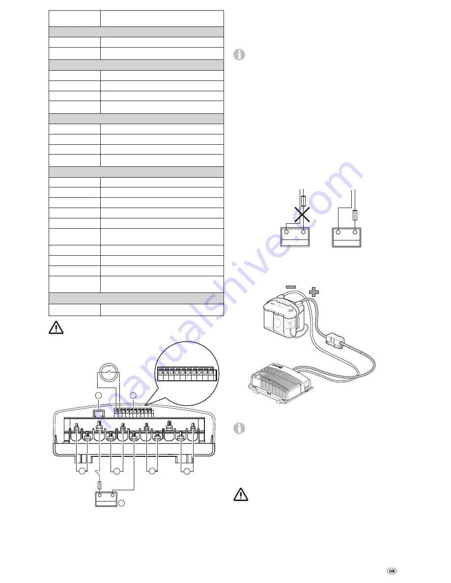
Figure 26
Once the cables have been routed out of the control unit, they
must be strain-relieved.
Connecting the drive motors
The data and motor cables must be routed together in such a
way that they cannot be torn off or damaged.
The cables may be shortened. Please pay attention to
different ring eyelet sizes.
Release the cover of the control unit by applying lateral press-
ure to the latching lugs, and clamp the cables as shown in
the connecting diagram
(red = positive, black = negative).
Please ensure that the connections are made properly. (Torque
M5 = 3.5 Nm / M6 = 6.0 Nm)
Connecting the battery
Liquid electrolyte batteries must be installed in a separate box
with ventilation leading to the outside. The fuse in the positive
lead must be connected outside the box. A separate box is
not required for gel or AGM batteries. Pay attention to the bat-
tery manufacturer's installation instructions.
The outgoing lines from the terminals must be routed with a
gap between them until after the fuse in the positive lead.
+
-
+
-
Figure 27
Route the battery connector cables (only use the original
Truma cables supplied) to the control unit and attach them
securely using the clips and screws provided.
Figure 28
The battery connector cables must not be extended.
They must be routed separately from the motor cables,
and must
not
run over the control unit.
Route battery connector cables so that they do not chafe (par-
ticularly at leadthroughs through metal panels). Use suitable
protective leadthrough bushing to prevent damage to cables.
Connect battery connector cables to the existing battery ter-
minals
(red = positive, black = negative).
Incorrect polarity will destroy the electronics / control
unit
The connection to the control unit (as per the connecting dia-
gram) must be made in the order: nut, battery connection ring
eyelet, nut (torque M6 = 6.0 Nm).
Connect fuse in the positive lead (150 A) near the positive
terminal.


