


66
Revision
8
–
November
2011
NOTE A: When adjusting leveling screws, nuts on
foundation bolts should be tightened only enough to
hold firmly. Final tightening is done after the unit is
grouted and the grout has set for at least 48 hours.
4.
Repeat steps 1 through 3 until indicator A reads
0.05 mm (.002 in.) or less.
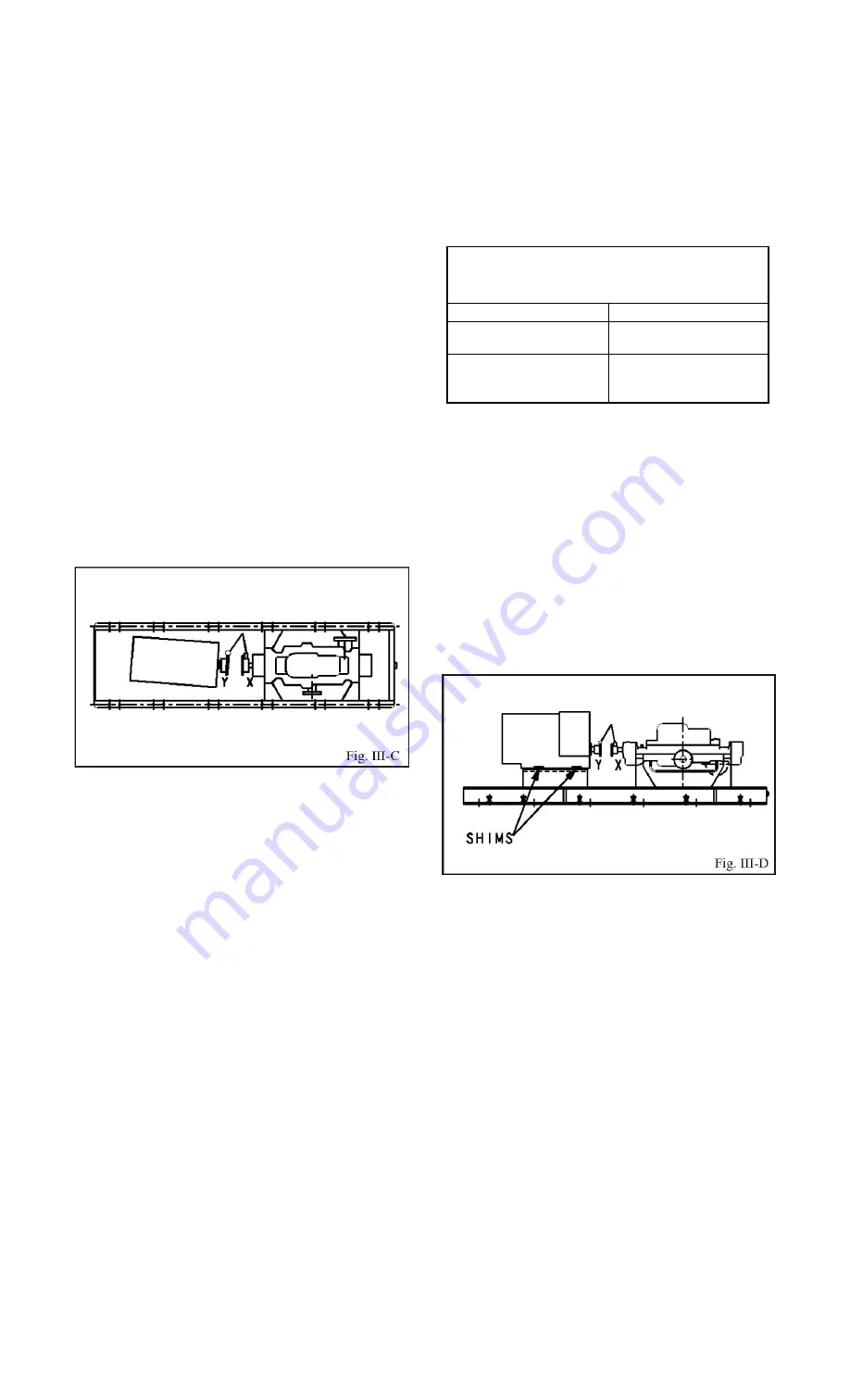
Horizontal Correction (Side-to-Side)
1
Zero indicator A on left side of coupling half Y, 90°
from top dead center (9 o’clock, Fig. III-C).
2
Rotate indicators/coupling halves through top dead
center to the right side, 180° from the start (3 o’clock). Observe
needle and record reading.
3a.
Negative Reading
-The coupling halves are
farther apart on the right (3 o’clock) side than the left (9
o’clock) side. Correct by sliding the shaft end of the
driver to the left or the opposite end to the right (Fig.
III-C).
3b.
Positive Reading
-The coupling halves are closer
together on the right (3 o’clock) side than the left (9
o’clock) side. Correct by either sliding the shaft end of the
driver to the right or the opposite end to the left (Fig. III-C).
NOTE: Drive trains of over 100 HP are supplied with
adjustment provisions fastened to the baseplate which
may be used to make all horizontal alignment
corrections.
4.
Repeat steps 1 through 3 until indicator A reads
0.05 mm (.002 in.) or less.
5.
Re-check both horizontal and vertical readings
to ensure adjustment of one did not disturb the other.
Correct as necessary.
PARALLEL ALIGNMENT
A unit is in parallel alignment when indicator P (parallel
indicator) does not vary by more than 0.05 mm (.002 in.) as
measured at four points 90° apart at operating temperature,
or when the shaft centerlines are within the recommended
cold setting criteria as shown in
Table III-1
.
Vertical Correction (Top-to-Bottom)
1
Zero indicator P at top dead center (12 o’clock)
of coupling half Y (Fig. III-D).
2
Rotate indicator/coupling halves to bottom dead
center (6 o’clock). Observe needle and record reading.
3a.
Negative Reading
-Coupling half X is lower
than coupling half Y. Correct by removing shims of
thickness equal to half of the indicator reading from
under each driver foot (Fig. III-D).
3b.
Positive Reading
-Coupling half X is higher than
coupling half Y. Correct by adding shims of thickness
equal to half of the indicator reading under each driver foot
(Fig. III-D).
NOTE: Equal amounts of shims must be added to or
removed from each driver foot, or the vertical angular
alignment will be affected.
4.
Repeat steps 1 through 3 until indicator P reads
0.05 mm (.002 in.) or less when hot, or per
Table III-1
when cold.
NOTE B: Shims that may be provided under the driver feet
should not be used to obtain satisfactory angular alignment
until after the grout has been poured and allowed to cure.
Table III-1 Cold Setting of Parallel
Vertical Alignment
Driver Type
Set Driver Shaft
Electric Motor
0.05 -0.10 mm LOW
(.002 -.004 in. LOW)
Turbine, Engine, etc.
Follow driver
manufacturer’s
recommendations
Summary of Contents for TSMP Series
Page 3: ...Revision 8 November 2011 3 PAGE SECTION...
Page 37: ...Revision 8 November 2011 37...
Page 46: ...46 Revision 8 November 2011 Assemble is reverse sequence of disassemble...
Page 54: ...54 Revision 8 November 2011 SECTIONAL Drawing of Typical TSMP...
Page 63: ...Revision 8 November 2011 63...


