background image

Support: 855-473-7449 or 408-943-4100                                     Email: 

[email protected]

Page 5

3.3  Install the Rack Rails

Before installing the rack rail, make sure the rack has enough space for the system� The ES24F needs 2U of space for 

both the system and rack rails, with the rack rails installed into the bottom 1U of the reserved space�

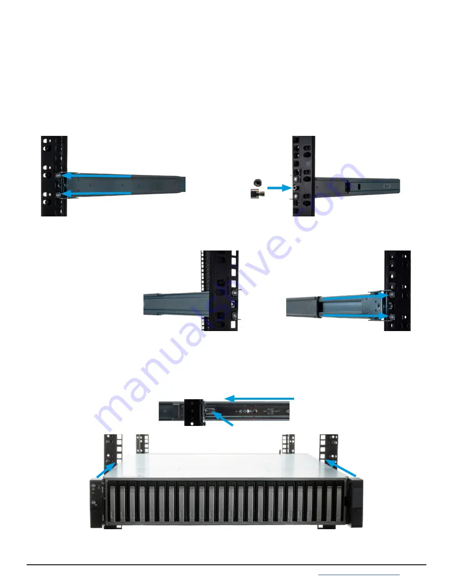
Take a rack rail and align the end stamped “FRONT” with the front of the rack� The “FRONT” text must be pointed 

in-

side

 the rack so the chassis rails can slide into the rack rails� Align the rail front pegs with the rack attach points and 

push the rail into the attach points� Fit the rail retention clip over the front of the rack by pushing on the spring plate 

to open the clip� The rail kit also includes two retention screw hole extenders that can be screwed into the middle 

rail attach point�

With the front of the rail installed, extend the back of the rack rail towards the equivalent attach points on the rear 

rack post� Make sure the rail remains level from front to back� Follow this process to install the other rack rail�

3.4  Push the System into the Rack

Team-lift the system and align the chassis rails with the rack rails� Slide the ends of the chassis rails into the rack 

rails and push the system forward until the metal safety catches click into place� Squeeze the safety catches against 

the sides of the system and continue to push the system forward until it is flush with the front of the rack.

The rail kit includes additional M4 screws that can be used to secure the system to the rack rails�

Retention 

Extender

Summary of Contents for ES24F

Page 1: ...TrueNAS ES24F Expansion Shelf Basic Setup Guide Version 1 0 ...

Page 2: ...ts 1 1 3 Unpacking the Unit 2 2 Ports and Indicators 3 3 Racking the ES24F 4 3 1 Rack Requirements 4 3 2 Chassis Rails 4 3 3 Install the Rack Rails 5 3 4 Push the System into the Rack 5 4 Handling Drives 6 4 1 Installing Drives into Trays 6 4 2 Inserting Drive Trays into the ES24F 6 5 Cabling 7 5 1 Connect Power Cords 7 5 2 Connect the Expansion Shelf 7 5 2 1 R Series 7 5 2 2 X Series 9 5 2 3 M Se...

Page 3: ...otect the internal components 3 Touch the metal chassis with your bare hand before touching any internal component including components not yet installed in the system This redirects static electricity in your body away from the sensitive internal com ponents Using an anti static wristband and grounding cable is another option 4 Store all system components in anti static bags More details about ES...

Page 4: ...55 GREP4 iX 855 473 7449 or 408 943 4100 Please locate and record the hardware serial numbers on the back of each chassis for quick reference Carefully unpack the shipping boxes and locate these components Accessory kit with 2 IEC C13 to NEMA 5 15P power cords 2 IEC C13 to C14 cords and a set of velcro cable ties DB9 to 3 5mm serial cable Set of rackmount rails with hardware Kit includes 2 rail re...

Page 5: ...erates an alert The back panel has several replaceable components From left to right the back panel has two power supplies PSU1 1 and PSU2 2 case fans FAN1 3 and FAN2 4 and expansion controller 1 5 and 2 6 Expansion controllers have several ports and indicators ES24F buttons and indicators are located on the ears on the right and left edges of the system front Each expansion controller has an ID b...

Page 6: ...outer rack rail and the inner chassis rail To protect it during shipping the chassis rail is inserted into the rack rail and must be removed before attaching to a system Slide the chassis rail forward until the metal catch stops it in place Push in the catch and continue to slide the chassis rail forward until it is free of the rack rail PUSH SLIDE Take the chassis rail and align the end stamped F...

Page 7: ...plate to open the clip The rail kit also includes two retention screw hole extenders that can be screwed into the middle rail attach point With the front of the rail installed extend the back of the rack rail towards the equivalent attach points on the rear rack post Make sure the rail remains level from front to back Follow this process to install the other rack rail 3 4 Push the System into the ...

Page 8: ...d drive side screw holes with the trays retention pegs Push the drive side screw holes into the fixed retention pegs 1 then into the flexible retention pegs 2 The drive will click into place To remove a drive push on the drive from the bottom of the tray to pop the drive out from the flexible retention pegs Continue to lift the drive free from the tray 4 1 Installing Drives into Trays 4 2 Insertin...

Page 9: ...with several TrueNAS systems Typical SAS cable connections for connecting two ES24F systems to various TrueNAS High Availability HA systems are shown here The typical connection order is SAS port 0 on the top ES24F expansion controller to the first SAS port on the pri mary TrueNAS Controller High Availability HA TrueNAS systems also connect the first SAS port on the secondary TrueNAS controller to...

Page 10: ...Support 855 473 7449 or 408 943 4100 Email support ixsystems com Page 8 R40 R50 ...

Page 11: ...Support 855 473 7449 or 408 943 4100 Email support ixsystems com Page 9 5 2 3 M Series 5 2 2 X Series ...

Page 12: ...o guide through configuring and using the software It is available by clicking Guide in the TrueNAS web interface or going directly to https www truenas com docs hub The TrueNAS Documentation Hub also provides an online version of this Guide and documentation of other iXsys tems products at https www truenas com docs hardware 6 Setting the ES24F Power Loss Mode If power is lost to the system the E...

Reviews: