24
Section 5: Maintenance
Before inspecting, cleaning or servicing the machine, shut off engine, wait for all moving parts to
come to a complete stop, disconnect spark plug wire and move wire away from spark plug. Remove
the key from the keyswitch on units so equipped.
Failure to follow these instructions can result in serious personal injury or property damage.
WARNING
NOTE: The unit will not cut properly if
there are protrusions on the mating sur-
faces of the cutter bar and blades.
CUTTER BLADE REASSEMBLY
Scissor action of cutter bar can easily
amputate fingers and toes. Be extremely
careful when sliding blade assembly out
of cutter bar assembly.
Slide blade assembly back into cutter bar
assembly. If blade assembly does not slide
readily, loosen screws (D, Fig. 5-11).
Put plastic blade guard on back onto
cutter bar assembly whenever cutter bar
is not in use.
CUTTER BAR HOLD-DOWN CLIP
ADJUSTMENT
Blades are very sharp! Wear heavy
leather gloves when working on or near
cutter blades. Failure to follow this
instruction may result in serious
personal injury.
Tighten hold-down clips every five oper-
ating hours, or when the unit is not cutting
effectively, or when the unit is excessively
noisy during normal operation. Best cut-
ting performance is obtained when there is
slight tension between hold-down clips (B,
Fig. 5-10) and wear plates (C).
Hold-Down Clip Tension Adjustment:
1. To increase tension on wear plate (C,
Fig. 5-10), loosen lock nuts (D) in hold-
down clip (B). Slide clip backward until it
contacts the wear plate. Re-tighten the
lock nuts.
2. Turn adjustment screw (F, Fig. 5-10)
clockwise to increase tension on cutter
blades (E). Hold-down clips should be
tight enough to prevent sloppy action, yet
allow the cutter bar assembly to slide
freely from side to side.
Blade/Ledger Plate Tightening:
1. Remove cutter bar assembly from unit
(see instructions earlier in this section).
2. Remove the blade assembly from the
cutter bar assembly (see instructions ear-
lier in this section).
3. Place the blade section with the loose
rivet(s) on a steel block or anvil. Position
the punch in the middle of the counter-
sunk area of the rivet (Fig. 5-14).
4. Strike the punch with the hammer,
expanding the rivet within the hole. Repeat
this procedure for all loose rivets in the
section.
5. If the blade (or ledger) section remains
loose, replace the rivets (see instructions
in this section).
HIGH-WEAR PARTS
Increased vibration or noise are indica-
tions of worn or damaged parts.
CHECKING THE ECCENTRIC RADIAL
BEARING/CHANNEL
The eccentric channel (A, Fig. 5-15) and
radial bearing (B) are high-wear parts.
Check for excessive wear at the end of
each mowing season. With engine off, and
spark plug wire disconnected, reach under
the unit and grasp the back of the eccen-
tric channel. Move the eccentric shaft (C,
Fig. 5-15) from side-to-side and back and
forth. If there is noticeable play in the
parts, replace the eccentric radial bearing
(B) and/or the eccentric arm (A).
ECCENTRIC RADIAL BEARINGS AND
CHANNEL REMOVAL/REPLACEMENT
Eccentric Radial Bearing and Channel
Removal:
1. Remove the six 5/16"-18 x 3/4" hex
head cap screws securing front fender.
Remove fender.
2. Remove eight screws securing eccen-
tric housing (M, Fig. 5-16) to engine deck.
3. Check the position of the eccentric
radial bearing (B, Fig. 5-16) in the eccen-
tric channel groove (A).
4. Position the radial bearing so it is all
the way back in the groove in the channel.
5. Remove the retaining ring (F, Fig. 5-16)
and bearing (B) from the eccentric shaft
and discard.
Eccentric Radial Bearing and Channel
Replacement:
Install a new bearing and retaining ring on
the eccentric shaft. Replace eccentric
housing (M). (See “Housing Assembly
Tightening Sequence” in this Section).
ECCENTRIC ARM WELDMENT/PARTS
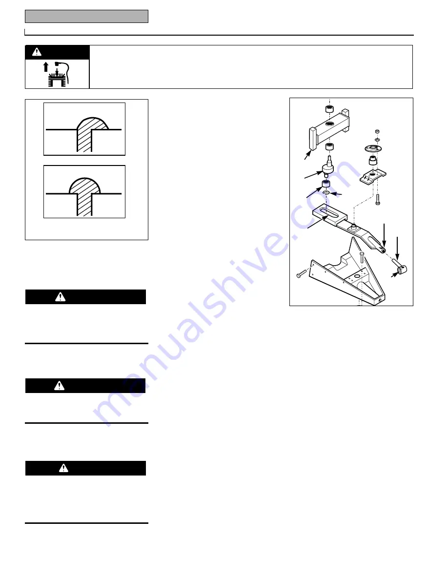
The eccentric arm weldment tube (D, Fig.
5-17), the pitman assembly shaft (E), and
the synthetic insert (F) can wear and will
eventually loosen. To check:
WARNING
DANGER
DANGER
IDEAL
UNACCEPTABLE
Fig. 5-14: Rivet Heads
A
B
C
H
G
D
E
F
Fig. 5-15


