background image

Section 5: Maintenance 

21

Before inspecting, cleaning or servicing the machine, shut off engine, wait for all moving parts to
come to a complete stop, disconnect spark plug wire and move wire away from spark plug.  Remove
the key from the keyswitch on units so equipped.
Failure to follow these instructions can result in serious personal injury or property damage.

WARNING

1.  Stop the engine, wait for all moving
parts to come to a complete stop, discon-
nect the spark plug wire and prevent it
from contacting the spark plug.
2.  Remove the hair pin cotters securing
the upper ends of the control rods to the
plastic thumb latches and wheel drive con-
trol levers (see J, Fig. 2-5).
3.  Thread the rods in or out of the idler
arm (A, Fig. 5-2) as needed. Adjust each
wheel drive control rod (A, Fig. 5-3) until
there is a 1-1/4" (32mm) gap between the
rod and the plastic thumb latch. Adjust
both control rods evenly.
4.  Re-install the hair pin cotters on the
outside of the wheel drive levers.

CUTTER BAR DRIVE BELT
REMOVAL/REPLACEMENT

Replace the cutter bar drive belt if it is
cracked, severely frayed, or worn to the
point where proper tension can no longer
be applied by the spring loaded idler.
1.  Stop the engine, wait for all moving
parts to come to a complete stop, discon-
nect the spark plug wire and prevent it
from contacting the spark plug.
2.  Put the cutter bar lever in the OFF posi-
tion (Fig. 4-7). Reach up underneath the
unit and remove the belt from the small
lower pulley (Fig. 5-4).

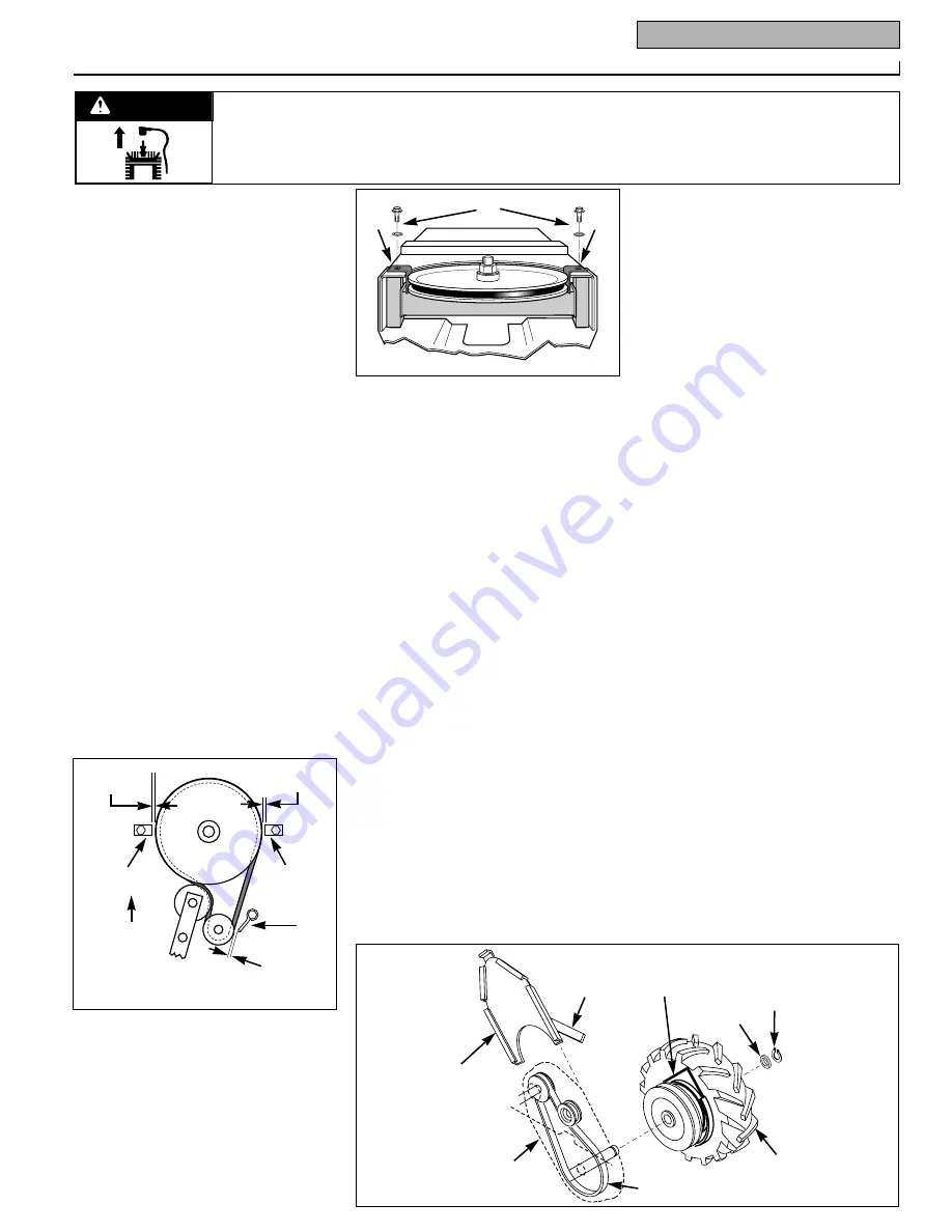
3.  Remove screws and washers (B, Fig. 5-
5) and both belt guides (A). Remove the
belt from the large pulley.
4.  Install new belt as shown in Fig. 5-4.
5.  Reinstall belt guides (A, Fig. 5-5) and
screws and washers (B). Adjust the guides
1/16" - 1/8" (1.6-3.2mm) away from belt.

CUTTER BAR BELT GUIDE 
ADJUSTMENT

1.  Stop the engine, wait for all moving
parts to come to a complete stop, discon-
nect the spark plug wire and prevent it
from contacting the spark plug.
2.  Place the belt under tension (Fig. 4-7)
by moving the cutter bar lever to the ON
position.
3.  Adjust front belt guides (Y, Fig. 5-4)
1/16"—1/8" (1.6—3.17 mm) away from
belt.
4. Secure guides.
5.  Adjust the right rear belt guide (Z) 1/4"
(6.35 mm) from the belt (Fig. 5-4).
6.  Secure the guide.

WHEEL DRIVE BELT 
ADJUSTMENT

Poor wheel traction can result if the belt
tension spring (B, Fig. 5-2) has loosened,
or if the wheel drive belt has worn.

To Adjust Wheel Belt Tension:
1.  Move the end of spring (B, Fig. 5-2),
located on the underside of the deck, to
the lower hole (C).
2.  If the belt tension is still too loose, the
spring or the belt may need replacing.

WHEEL DRIVE BELT
REMOVAL/REPLACEMENT

When a wheel drive belt is frayed, broken
or worn to the point where tension can no
longer be controlled with the idler pulley,
the belt or spring must be replaced.
NOTE:  Prop the unit up by placing sturdy
supports under the engine deck.

To Remove the Wheel Drive Belt:
1.  Remove drive belt cover (A, Fig. 5-6).
2.  Remove snap ring (B) and washer (C)
from drive axle.
3.  Remove wheel assembly (F).
4.  Slip the drive belt off the pulleys and
off the unit.
To Replace the Wheel Drive Belt:
1.  Slide wheel assembly (F, Fig. 5-6) onto
axles. Note that seal tabs (AA) fit inside
the belt guard (J).
2.  Route belt (E) into place around pulley
on wheel assembly (F).
3.  Secure wheel with washer (C) and snap
ring (B) removed earlier.
4.  Install drive belt cover assembly (A).
Note that finger (H) on drive belt cover
points toward the front of the unit.

WHEEL DRIVE BELT GUIDE 
ADJUSTMENT

1.  Place belt under tension by engaging
wheel drive clutch lever. See Fig. 4-5.
2.  Remove Drive Belt Cover (A, Fig. 5-6).
3.  Adjust belt guide (A, Fig. 5-7) to 1/16”
(1.6mm) or less away from belt. 
4.  Adjust belt guide (B) 1/4” (6.4mm)
away from pulley (D).
5.  Tighten belt guide (B) at bolt (C) after
adjusting.
6.  Install belt cover (A, Fig. 5-6).

A

A

B

Fig. 5-5

A

H

J

E

F

C

B

AA

Fig. 5-6

1/16"-1/8"

(1.6-3.2mm)

1/4"

(6.4mm)

FRONT

Fig. 5-4

Y

Y

Z

1/16"-1/8"

(1.6-3.2mm)

Summary of Contents for 34061

Page 1: ...st GARDEN WAY INCORPORATED Models 34061 34 3 1 2 HP Recoil Start 34062 38 4HP Recoil Start 34337 34 4HP Recoil Start 34063 42 5HP Recoil Start 34064 42 5HP Electric Start SAFETY FIRST Before operating...

Page 2: ...ce Controls OPC 14 Wheel Drive Levers 14 Engine Oil Dipstick Fill Hole 14 Shoes 14 Cutter Bar with guard 15 Fuel Tank Cap 15 Starter Rope Handle 15 Engine Keyswitch electric start units 15 Cutter Bar...

Page 3: ...ewelry scarves ties etc which may get caught in moving parts Tie up or restrain hair c Do not operate the unit while bare foot Do not wear sandals d Wear long trousers e Wear hearing protection 2 Do n...

Page 4: ...r installing the plastic blade protector shut the engine off disconnect the spark plug wire and prevent it from touching the spark plug On electric start models also remove the ignition key from the k...

Page 5: ...can ignite spilled fuel or oil 9 If the unit has gasoline in its fuel tank do not store it inside a building where fumes from the gasoline could reach an open flame or spark Let the engine cool before...

Page 6: ...r bar Do not place fingers between blades Amputation could result UNPACKING THE UNIT The cutter bar blade and attached plastic blade guard are packaged separately within the main shipping crate Leave...

Page 7: ...cription Qty Right Handlebar shipped connected to unit by wiring 1 Left Handlebar shipped connected to unit by wiring 1 1 Hex Head Capscrew 5 16 18 x 2 1 4 2 2 Toplock Nuts 5 16 18 to mount handlebars...

Page 8: ...optional not shown 1 31 Key In Keyswitch optional not shown 1 18 19 21 20 25 27 24 22 23 26 12 Ref Description Qty 11 Loctite Thread Fastener bottle or tube 1 12 Hex Cap Screw 3 8 16 x 1 1 4 Grade 8 3...

Page 9: ...handlebar ends act as shock absorbers and also help reduce vibration WHEEL DRIVE CONTROL ROD INSTALLATION 1 Place the control rods D Fig 2 4 BETWEEN the handlebars and UNDER the bridge with the thread...

Page 10: ...levers on the handlebars and carefully roll the unit from off the shipping crate Park the unit on a flat clean surface where you can complete the remaining assembly steps CUTTER BAR ASSEMBLY AND INST...

Page 11: ...ff the ground Securely attach the cutter bar and doubler bracket to the cutter bar mounting bracket with the three hex cap screws E 3 8 flat washers F and 3 8 16 center locknuts G Torque to 35 ft lbs...

Page 12: ...ned washers K on the screws Securely attach the knife head to the cutter bar with the two screws torque to 16 20 ft lbs if you have a torque wrench 12 At the inner set of mounting holes M Fig 2 11 pos...

Page 13: ...the unit Use of any other battery charger may damage the battery Do not short circuit the battery by touching the connectors or wires together or by touching metal objects against the connectors Remov...

Page 14: ...LEVERS The wheel drive levers C Fig 3 1 are located beneath the handgrips on each handlebar and control the wheel drive belt system Squeezing the levers disengages the drive belt and allows the unit...

Page 15: ...wheel screen The starter rope handle is used to pull start the engine NOTE Electric start models can also be pull started with the starter rope J ENGINE KEYSWITCH ELECTRIC START UNITS ONLY The engine...

Page 16: ...formation 1 Unscrew the fuel tank cap A Fig 4 1 Add gasoline Leave at least two inches of space below the filler neck to allow room for expansion 2 Re install the cap Wipe up spilled gasoline ADJUST T...

Page 17: ...ESENCE CONTROL OPC SYSTEM TEST If the engine does not stop when either Operator Presence Control OPC lever is released stop the engine and wait for all moving parts to come to a complete stop Move the...

Page 18: ...ed along the cutter bar and set at different heights to accommodate unusual terrain conditions NOTE Shoes are not always necessary particularly when mowing lush green veg etation on even terrain free...

Page 19: ...e Mow with the carburetor on the high side to help prevent oil spillage Failure to follow these instructions may result in personal injury or property damage Keep the oil level at FULL especially when...

Page 20: ...5 1 will remain on the axle 4 Clear grass or other matter from the exposed areas To Re Assemble 1 Slide wheel tire assembly C Fig 5 1 onto axle Note that belt seal tabs F fit inside the belt guard D 2...

Page 21: ...complete stop discon nect the spark plug wire and prevent it from contacting the spark plug 2 Place the belt under tension Fig 4 7 by moving the cutter bar lever to the ON position 3 Adjust front belt...

Page 22: ...hese instructions may result in serious personal injury or prop erty damage NOTE An assistant should stand in the operator position and firmly hold the han dlebars while the cutter bar is being remove...

Page 23: ...same cutting angle as the original sharpened edge File or grind only the top angled surface of the blade The bottom edge of the blade must remain flat to provide good shearing action BLADE SECTION OR...

Page 24: ...ction 2 Remove the blade assembly from the cutter bar assembly see instructions ear lier in this section 3 Place the blade section with the loose rivet s on a steel block or anvil Position the punch i...

Page 25: ...fore attempting this repair or have the unit serviced by your authorized dealer NOTE Raise and support the unit from underneath To Remove the Eccentric Shaft Bearings 1 Clamp the eccentric housing M F...

Page 26: ...eccentric shaft with the 5 8 18 hex nut H Fig 5 16 and 5 8 flat washer J removed earlier on the top of the eccentric shaft C 5 Tighten securely ENGINE MAINTENANCE CHECK ENGINE OIL LEVEL Before starti...

Page 27: ...he battery charger A Fig 5 20 from the wall outlet 2 Plug the battery wire lead B into the battery charger lead C 3 Plug the battery charger into a grounded 120 volt wall outlet The battery charger is...

Page 28: ...gasoline stabilizer or drain gasoline outdoors into an approved container Do not smoke and keep away from open flame Never store the unit with fuel in the fuel tank inside a building where fumes may r...

Page 29: ...See engine service dealer 10 Defective wheel drive or cutter bar 10 Inspect wires See engine service dealer switch or wiring to replace switch Engine runs poorly 1 Defective spark plug 1 Replace spark...

Page 30: ...2 50 51 312 53 303 52 319 321 318 321 2 12 9 306 117 118 11 13 119 10 3 301 155 12 156 4 115 116 313 112 10 5 7 9 27 29 22 22 23 34 311 36 60 35 128 93 82 57 38 37 107 31 39 162 95 41 46 49 163 48 45...

Page 31: ...3 8 24 6 57 1100044 Hex Hd Capscrew 5 16 18 x 3 4 3 60 1120210 Roll Pin 3 16 x 1 1 61 1186469 Carriage Bolt 5 16 18 x 3 4 2 81 1773272 Flat Washer hardened 5 16 2 82 1100255 Flat Washer 5 16 5 84 177...

Page 32: ...3 72 88 87 86 16 17 74 33 57 17 75 57 92 90 162 310 307 119 148 308 309 137 153 145 152 141 142 140 138 76 57 178 84 106 122 77 108 318 317 319 83 33 162 81 80 130 178 79 108 74 17 16 89 17 57 143 81...

Page 33: ...104 1740496 Self Tapping Screw 5 16 18 x 5 8 6 106 1100806 Hex Hd Capscrew 1 4 20 x 1 1 4 1 108 1767609 Grease Fitting 1 4 28 x 90 2 109 1766704 Upper Hook 1 4 20 1 111 1766805 Weed diverter Strap 14...

Page 34: ...13 13 13 5 9 9 9 9 9 18 18 18 18 18 150 24 14 14 14 14 31 31 31 31 29 150 24 126 170 127 129 18 18 18 18 18 18 Items not Included in Cutter Bar Assemblies 1765990 1766743 1766744 1 3 4 3 2 1 3 4 3 2...

Page 35: ...42 Blade Assembly Incl Refs 6 7 8 9 10 11 1 24 1107382 Flat Washer 5 16 4 29 1766777 Blade Guard 34 1 1766934 Blade Guard 38 1 1766935 Blade Guard 42 1 31 1766768 Hex Hd Screw M8 x 45 8 120 1773057 K...

Page 36: ...umbers of the unit Replacement Parts Factory specified replacement parts are available from your authorized dealer or directly from the factory When ordering parts be sure to provide the following Mod...

Reviews: