10
3. Operation Panel
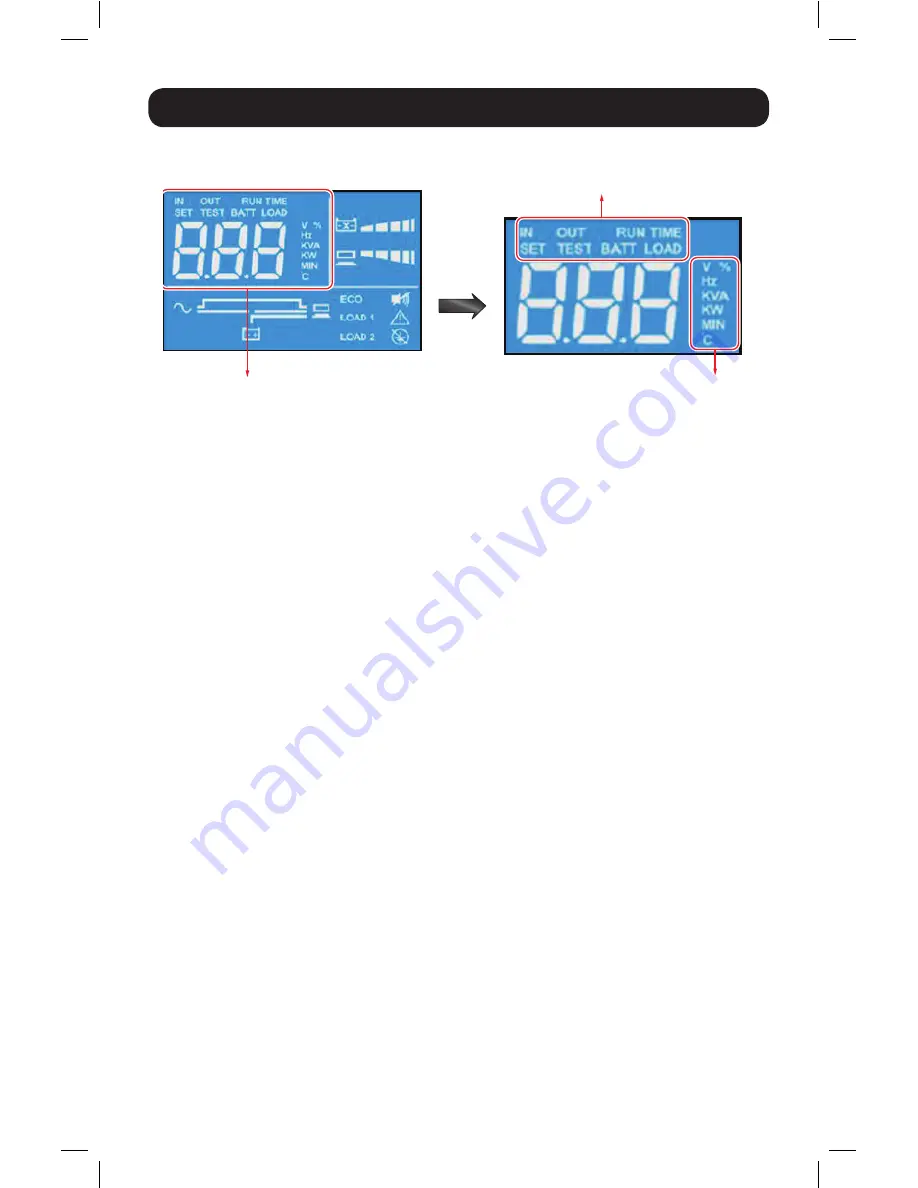
3.4 7-Segment Display
7-Segment Display
Row A
Column B
Note:
Read the text shown in Row A together with that in Column B to understand the display meaning.
IN
1. IN & V:
When the two illuminate together, it indicates input voltage.
2. IN & Hz:
When the two illuminate together, it indicates input frequency.
OUT
1. OUT & V:
When the two illuminate together, it indicates output voltage.
2. OUT & Hz:
When the two illuminate together, it indicates output frequency.
RUN TIME
RUNTIME & MIN:
When the two illuminate together, it indicates the estimated remaining battery
backup time.
SET
When the word ‘SET’ illuminates, it indicates the UPS is in setup mode.
You can adjust the following through the LCD. For setup instructions, refer to the Setup Mode Flow
Chart in
Section 5.6
.
1. Inverter voltage
2. Inverter frequency
3. Bypass range
4. Economy mode
5. Alarm disable
6. Overload alarm
TEST
1. When the word ‘TEST’ flashes, it means that the UPS is under self test.
2. When the words ‘TEST’ and ‘BATT’ flash together, it indicates the UPS is under battery self test.
BATT
1. BATT & %:
When the two illuminate together, it indicates the remaining battery capacity.
2. BATT & V:
When the two illuminate together, it indicates battery voltage.
18-09-252-93358B.indb 10
1/9/2019 2:19:28 PM


