background image

115

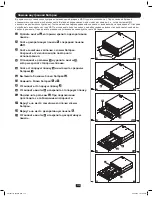
Замена внутренней батареи

В нормальных условиях эксплуатации оригинальные батареи в ИБП служат несколько лет. Перед заменой батарей 

ознакомьтесь с разделом по безопасности. Батареи предназначены для «горячей» замены (т.е., когда система ИБП 

находится в режиме эксплуатации). Тем не менее, квалифицированный специалист, вызванный для проведения ТО, вправе 

потребовать выключить систему ИБП и отсоединить подключенное к ней оборудование в качестве дополнительной меры 

предосторожности. Перед началом процесса установки рекомендуется снять батареи.

1


Удалить винты 

A

, которыми крепится декоративная 

панель.

2


Снять декоративную панель 

B

 с передней панели 

ИБП.

3


Снять защитные колпачки с клемм батареи. 

Сохранить эти колпачки для повторного 

использования.

4


Отсоединить разъемы 

C

 и удалить винты 

D

которые крепят стопорные планки.

5


Снять стопорную планку 

E

 и вытащить среднюю 

батарею 

F

.

6


Вытащить боковые блоки батарей 

G

.

7


Заменить блоки батарей 

F

 и 

G

.

8


Установить стопорную планку 

E

.

9


Установить винты 

D

 и закрепить стопорную планку.

10


Подключить разъемы 

C

. При подключении 

проследить за соблюдением полярности.

11


Вернуть на место защитные колпачки клемм 

батареи.

12


Вернуть на место декоративную панель 

B

.

13


Установить винты 

A

 и закрепить декоративную 

панель.

1

13

2

12

4

9-10

5

7-8

6

7

A

B

C

D

D

E

G

G

F

201207113 933070.indb   115

9/17/2012   1:21:29 PM

Summary of Contents for SmartOnline 5KVA-6KVA

Page 1: ...les 6kVA Rackmount and tower adaptable Not suitable for mobile applications Important Safety Warnings 2 Mounting 3 Connection 9 Features 4 Internal Battery Replacement 28 Espa ol 30 Storage and Servic...

Page 2: ...gh short circuit current Observe proper precautions Do not dispose of the batteries in a fire Do not open the UPS or batteries Do not short or bridge the battery terminals with any object Unplug and t...

Page 3: ...he UPS prior to installation This will remove excess weight and will allow safer handling of equipment See Internal Battery Replacement section for battery removal instructions Mount your equipment in...

Page 4: ...you to browse through different options and power readings on the LCD display Momentarily pressing it causes the LCD screen to display a different power reading see Operation Section Pressing it and...

Page 5: ...232 RS 232 ACC SLOT AC INPUT BATTERY CABLE UNDER LOAD DO NOT DISCONNECT 192VDC CONNECTOR BATTERY CAUTION BREAKER 20A OUTPUT 2 200 240Vac OUTPUT 1 200 240Vac 30A USB 14 EPO PARALLEL RS 232 RS 232 ACC...

Page 6: ...Modules Note See the manual included with the Parallel PDU for 12kVA installation configuration and setup instructions EPO PARALLEL RS 232 RS 232 USB EPO PARALLEL RS 232 RS 232 USB EPO PARALLEL RS 23...

Page 7: ...0RT4UTF 6kVA UPS with NEMA PDU and 6KVA Isolation Transformer EPO PARALLEL RS 232 RS 232 ACC SLOT USB NORMAL BY PASS 16 15 SU6000RT4UTFHW 6kVA UPS with Hardwire PDU and 6kVA Isolation Step Down Transf...

Page 8: ...s and shut down equipment during a blackout See Optional Connection section for details 10 Mini Slot USB connector disabled by default DIP switches in the RS 232 position to enable move both DIP switc...

Page 9: ...mode 5 UPS Cold Start Optional To use your UPS as a stand alone power source when AC input power is unavailable i e during a blackout you can cold start your UPS and power connected equipment from th...

Page 10: ...ound wires Hardwire In Receptacle Out according to markings on the connectors as seen in diagram 2 3 Slide in and reattach the terminal strip cover with the 3 screws from Step 1 4 Attach the PDU to th...

Page 11: ...set to the output terminals Hardwiring the Transformer Bundle Input Output Set Front Panel Selector Switch to Proper Voltage Before Making Connections 208 240V Input 120V Output Branch A 120V Output...

Page 12: ...simultaneously with the USB communication module 2 EPO Port Connection This optional feature is only for those applications that require connection to a facility s Emergency Power Off EPO circuit When...

Page 13: ...Serial SNMP USB LCD Screen OFF OFF OFF OFF OFF OFF Emergency Stop To restart the UPS unit after asserting EPO without AC line power 1 Verify that the EPO assertion has been removed or cleared 2 Reappl...

Page 14: ...UPS s OFF button B if the UPS is powered until you hear a beep and see a BYPASS MODE message shown in its LCD Display C on the front of the power module You will be prompted to enter BYPASS MODE Press...

Page 15: ...n Mode With an EPO shutdown with no output present you will see the following LED sequence EPO Shutdown AC Mode With an EPO shutdown having AC power present you will see the following LED sequence Bat...

Page 16: ...OLD START BAD BATTERY CALL FOR SERVICE CHARGE BATT FAIL CALL FOR SERVICE AC DC FAILURE CALL FOR SERVICE INVERTER FAILURE CALL FOR SERVICE OUTPUT FAILURE CALL FOR SERVICE FAN FAILURE CALL FOR SERVICE D...

Page 17: ...more information The second line of the LCD Display shows basic power conditions In each operating mode you can push the SCROLL buttons to browse through these basic power conditions in the sequences...

Page 18: ...nged by the administrator The DEFAULT password is 1234 NOTE When two units are connected in parallel the Master UPS will display PARALLEL MASTER in this second screen The display on the Secondary UPS...

Page 19: ...SETTING screen Press ON to get to the CHANGE PASSWORD screen and DOWNi to get to the LANGUAGE screen From here press ON You can then scroll DOWNi or UPh through languages until you find your desired l...

Page 20: ...RGER CURRENT screen Press ON again From here you can scroll DOWNi or UPh to select current values between 0 7 and 4 0 A Press ON to save your desired value The DEFAULT selection is 0 7A Use the follow...

Page 21: ...Here press ON Now you can scroll DOWNi or UPh between NO TEST 30 60 90 days and QUICK TEST When you reach your desired time length press ON to save The DEFAULT is NO TEST Operation continued BATTERY...

Page 22: ...u reach the OUTPUT SETTING screen Press ENTER for the OUTPUT VOLTAGE screen and DOWNi to access the FREQ CONVERTER screen Here press ON Now you can scroll DOWNi or UPh between DISABLE 50 and 60 Hz Pre...

Page 23: ...the UPS will transfer to Bypass Mode returning to On Line Mode when the output is back to normal From the STARTUP MENU screen scroll DOWNi until you reach the OUTPUT SETTING screen From here press ON...

Page 24: ...e last 5 fault events Press ON to exit this menu Erase All Used to clear the Fault Event Log From the STARTUP MENU scroll DOWNi until you reach the UPS ALARM LOG screen From here press ON to reach the...

Page 25: ...AGNOSTIC MODE INPUT 000V 00Hz DIAGNOSTIC MODE INPUT 000V 00Hz DIAGNOSTIC MODE RECTIFIER OK DIAGNOSTIC MODE RECTIFIER OK DIAGNOSTIC MODE CHARGER OK DIAGNOSTIC MODE BATTERY OK DIAGNOSTIC MODE BATTERY OK...

Page 26: ...inuously To silence the On Battery Alarm press the ON MUTE button Overload Messages When the UPS detects an output overload its LCD will switch to the following display The UPS will then begin a count...

Page 27: ...ut Fuse Open Output Fuse Open Parallel Wire Connection Failure SHUTDOWN CONDITIONS LCD DISPLAY MESSAGES Internal Faults SHUT DOWN OVERLOAD XXX SHUT DOWN O P SHORT CIRCUIT SHUT DOWN BYPASS SCR FAIL SHU...

Page 28: ...covers Save these covers for reuse 4 Disconnect the battery connectors C and remove the screws D that secure the battery retention bracket in place 5 Remove the battery retention bracket E and remove...

Page 29: ...n shipping charges Visit www tripplite com support before sending any equipment back for repair THIS WARRANTY DOES NOT APPLY TO NORMAL WEAR OR TO DAMAGE RESULTING FROM ACCIDENT MISUSE ABUSE OR NEGLECT...

Page 30: ...sistema UPS con sistema de bater as internas 5 6kVA PDU desmontable y m dulos PDU paralelos desmontables 6kVA Adaptable para montar en rack y en torre No es adecuado para aplicaciones m viles Instrucc...

Page 31: ...usar quemaduras por cortocircuitos de alta tensi n Tome las precauciones necesarias No deseche las bater as en el fuego No abra el UPS ni las bater as No haga cortocircuito ni puente en los terminales...

Page 32: ...tes de la instalaci n es recomendable retirar las bater as internas del UPS Esto eliminar el peso excesivo y permitir un manejo m s seguro del equipo Consulte la secci n de Reemplazo de la Bater a Int...

Page 33: ...e este modo 4 BOT N SCROLL UP SELECT Desplazarse hacia arriba Seleccionar Este bot n permite examinar distintas opciones y lecturas de energ a en la pantalla LCD Si lo pulsa moment neamente el LCD mos...

Page 34: ...s de la caracter stica 1 EPO PARALLEL RS 232 RS 232 ACC SLOT AC INPUT BATTERY CABLE UNDER LOAD DO NOT DISCONNECT 192VDC CONNECTOR BATTERY CAUTION BREAKER 20A OUTPUT 2 200 240Vac OUTPUT 1 200 240Vac 30...

Page 35: ...sistema de 12kVA consulte el manual incluido con el PDU Paralelo Consulte la secci n Caracter sticas Panel trasero para observar las descripciones de la caracter stica EPO PARALLEL RS 232 RS 232 USB E...

Page 36: ...UPS de 6kVA con PDU Con Instalaci n El ctrica Permanentemente y Transformador Reductor de Aislamiento de 6kVA SU6000XFMR2U SU6000RT4UTF UPS de 6kVA con PDU NEMA y Transformador de Aislamiento de 6kVA...

Page 37: ...equipo en caso de un apag n Consulte la secci n Conexi n opcional para obtener detalles 10 Miniranura Conector USB desactivado en forma predeterminada interruptores DIP en la posici n RS 232 Para acti...

Page 38: ...a cambiar el voltaje de salida del UPS consulte Selecci n del voltaje de salida de la secci n Funcionamiento Debe seleccionar el voltaje de salida correcto antes de conectar los equipos al UPS Conexio...

Page 39: ...exi n permanente Salida de recept culo de acuerdo a las marcas de los conectores como se muestra en el diagrama 2 3 Deslice hacia adentro y vuelva a unir la cubierta de la banda de terminales con los...

Page 40: ...tomacorrientes o ambas previendo que la carga conectada no exceda la capacidad SU12KRT4UHW Para la conexi n puesta a punto e instalaci n consulte el manual incluido con el PDU Paralelo 2 Conecte los...

Page 41: ...icaci n USB 2 Conexi n del puerto EPO Esta caracter stica opcional es nicamente para aquellas aplicaciones que requieran conexi n a un circuito de Apagado de Emergencia EPO de la instalaci n Cuando se...

Page 42: ...tema de bater as interno las bater as externas s lo son necesarias para extender el tiempo de funcionamiento Si agrega bater as externas aumentar el tiempo de recarga y el tiempo de funcionamiento La...

Page 43: ...el UPS PASO 2 Si el UPS recibe energ a pulse el bot n B OFF del UPS hasta que escuche un pitido y el mensaje BYPASS MODE modo de derivaci n aparezca en la pantalla LCD C en el frente del m dulo de pot...

Page 44: ...fre cuencia Con apagado EPO sin alimentaci n observar la siguiente secuencia de LED Apagado EPO Modo CA Con apagado EPO y con alimentaci n CA observar la siguiente secuencia de LED Modo de Bater a Ind...

Page 45: ...A MANTENIMIENTO FALL LA CARGA DE LA BATER A LLAME A MANTENIMIENTO FALLA DE CA CC LLAME A MANTENIMIENTO FALLA DEL INVERSOR LLAME A MANTENIMIENTO FALLA DE SALIDA LLAME A MANTENIMIENTO FALLA DEL VENTILA...

Page 46: ...ormaci n adicional consulte el manual proporcionado con el juego del PDU Paralelo La segunda l nea de la pantalla LCD muestra las condiciones de alimentaci n b sicas En todos los modos de funcionamien...

Page 47: ...ngo para la contrase a es 0000 9999 y el administrador debe cambiarlo La contrase a PREDETERMINADA es 1234 Funcionamiento continuaci n NOTA Cuando se conectan dos unidades en paralelo el UPS Maestro m...

Page 48: ...pantalla CONFIGURACI N B SICA Pulse ON para ir a la pantalla CAMBIO DE CONTRASE A y HACIA ABAJO para acceder a la pantalla de IDIOMA Pulse ON Luego puede desplazarse HACIA ABAJO o HACIA ARRIBA a trav...

Page 49: ...NTE DEL CARGADOR Pulse ON nuevamente Aqu puede desplazarse HACIA ABAJO o HACIA ARRIBA para seleccionar valores de corriente entre 0 7 y 4 0 A Pulse ON para guardar el valor deseado La selecci n PREDET...

Page 50: ...PRUEBA DE DESCARGA Pulse ON Ahora puede desplazarse HACIA ABAJO o HACIA ARRIBA entre SIN PRUEBA 30 60 90 d as y PRUEBA R PIDA Cuando alcance la longitud de tiempo deseada pulse ON para guardar El VAL...

Page 51: ...JO hasta llegar a la pantalla CONFIGURACI N DE LA SALIDA Pulse INTRO para acceder a la pantalla VOLTAJE DE SALIDA y HACIA ABAJO para acceder a la pantalla CONVERSOR DE FREC Pulse ON Ahora puede despla...

Page 52: ...se transferir al Modo de derivaci n volviendo al Modo en l nea cuando la salida vuelva a ser normal Desde la pantalla MEN DE INICIO despl cese HACIA ABAJO hasta llegar a la pantalla CONFIGURACI N DE L...

Page 53: ...AJO o HACIA ARRIBA para leer los 5 ltimos eventos de fallas Pulse ON para salir de este men Borrar todo Se utiliza para borrar el Registro de eventos de fallas Desde la pantalla MEN DE INICIO despl ce...

Page 54: ...ODO DIAGN STICO ENTRADA 000V 00Hz MODO DIAGN STICO ENTRADA 000V 00Hz MODO DIAGN STICO RECTIFICADOR OK MODO DIAGN STICO RECTIFICADOR OK MODO DIAGN STICO CARGADOR OK MODO DIAGN STICO BATER A OK MODO DIA...

Page 55: ...st n por agotarse el m dulo de potencia del UPS emitir un pitido continuamente Para silenciar la Alarma de la bater a pulse el bot n ON MUTE Mensajes de sobrecarga Cuando el UPS detecta una sobrecarga...

Page 56: ...de salida Fusible de entrada abierto Fusible de salida abierto Falla de conexi n del cable paralelo CONDICIONES DE APAGADO MENSAJES DE LA PANTALLA LCD Fallas internas APAGADO SOBRECARGA XXX APAGADO C...

Page 57: ...onecte los conectores de la bater a C y extraiga los tornillos D que aseguran el soporte de retenci n de la bater a en su lugar 5 Extraiga el soporte de retenci n de la bater a E y extraiga recicle el...

Page 58: ...cio t cnico bajo esta garant a solo puede ser obtenido si usted entrega o env a el producto con todos los cargos de env o o entrega prepagos a Tripp Lite 1111 W 35th Street Chicago IL 60609 EE UU El v...

Page 59: ...un syst me UPS avec un module de batterie interne 5 6kVA PDU amovible et modules PDU parall les amovibles Montage en rack et compatible avec montage en tour Non appropri pour les applications mobiles...

Page 60: ...atteries au feu N ouvrez ni l UPS ni les batteries N tablissez pas de court circuit ou de pont entre les bornes de la batterie et un objet quelconque D branchez et mettez votre UPS sous tension avant...

Page 61: ...s et du fait m me une manutention plus s curitaire de l quipement Consulter la section Remplacement des batteries pour des instructions sur le retrait des batteries 4 l aide d un assistant soulevez l...

Page 62: ...nfiguration et pour sortir du mode configuration 4 BOUTON SCROLL UP SELECT ce bouton vous permet de parcourir les diff rentes options et de voir la puissance sur l affichage LCD Lorsque vous appuyez s...

Page 63: ...bl 1 EPO PARALLEL RS 232 RS 232 ACC SLOT AC INPUT BATTERY CABLE UNDER LOAD DO NOT DISCONNECT 192VDC CONNECTOR BATTERY CAUTION BREAKER 20A OUTPUT 2 200 240Vac OUTPUT 1 200 240Vac 30A USB 14 EPO PARALLE...

Page 64: ...PDU parall les Remarque Voir le manuel inclus avec le PDU parall le pour des instructions concernant l installation la configuration et le r glage 12 kVA EPO PARALLEL RS 232 RS 232 USB EPO PARALLEL RS...

Page 65: ...4 5 10 9 1 2 11 12 13 14 8 24 24 25 SU6000RT4UTFHW ASC 6 kVA avec PDU raccordement fixe et le transformateur abaisseur d isolation 6 kVA SU6000XFMR2U SU6000RT4UTF ASC 6 kVA avec PDU NEMA et transform...

Page 66: ...panne Voir Raccordement optionnel pour plus de d tails 10 Mini slot connecteur USB d sactiv par d faut commutateurs DIP en position RS 32 pour activer le d placement des deux commutateurs DIP sur la p...

Page 67: ...tre effectu par un lectricien qualifi Lorsque vous effectuez les raccordements de c bles veuillez respecter les r glementations en mati re de raccordement des c bles en vigueur dans votre r gion par...

Page 68: ...s de raccordement et la refixer l aide des trois vis comme dans l tape 1 4 Fixer le PDU sur le syst me UPS l aide des 4 vis comme dans le dessin 4 Branchement des barrettes de raccordement Module PDU...

Page 69: ...dition que la charge combin e ne d passe pas la capacit SU12KRT4UHW Voir le manuel inclus avec le PDU pour des renseignements concernant la connexion le r glage et l installation 2 Brancher les 2 jeux...

Page 70: ...aract ristique en option est seulement pour les applications qui n cessitent une connexion un circuit de mise hors tension d urgence EPO d une installation Lorsque l ASC est connect e ce circuit elle...

Page 71: ...alimentation c a DEL Sortie Ventilateurs S rie SNMP USB CRAN ACL OFF hors tension OFF hors tension OFF hors tension OFF hors tension OFF hors tension OFF hors tension Arr t d urgence Pour red marrer l...

Page 72: ...de l UPS TAPE 2 Appuyez sur le bouton B OFF de l UPS si l UPS est en marche jusqu ce que vous entendiez un bip et voyiez appara tre BYPASS MODE mode d rivation sur l cran LCD C l avant du bloc de puis...

Page 73: ...imentation en sortie voici la s quence DEL que vous obtiendrez Arr t d urgence Mode CA avec un arr t d urgence avec alimentation voici la s quence DEL que vous obtiendrez En mode ind pendant batterie...

Page 74: ...RIE SOLLICITEZ DES R PARATIONS D FAILLANCE CHARGE BATTERIE SOLLICITEZ DES R PARATIONS CHEC CA CC SOLLICITEZ DES R PARATIONS CHEC ONDULEUR SOLLICITEZ DES R PARATIONS CHEC PUISSANCE DE SORTIE SOLLICITEZ...

Page 75: ...6kVA ou s alimenter jusqu 12kVA Se reporter au manuel fourni avec l ensemble PDU parall le pour plus de renseignements La seconde ligne de l cran LCD affiche les param tres du courant de base Appuyez...

Page 76: ...ans la plage 0000 9999 et doit tre modifi par l administrateur Le mot de passe PAR D FAUT est 1234 Utilisation suite Remarque Lorsque deux unit s sont connect es en parall le l UPS Ma tre affichera Pa...

Page 77: ...cran BASIS SETTING param tres de base Appuyez sur ON pour voir l cran CHANGE PASSWORD modifier mot de passe et descendez jusqu l cran LANGUAGE langue Ensuite appuyez sur ON Vous pouvez ensuite parcour...

Page 78: ...ite sur ON pour atteindre l cran CHARGER CURRENT courant du chargeur Appuyez nouveau sur ON Vous pouvez ensuite utiliser les boutons DOWN et UP pour s lectionner les valeurs de courant entre 0 7 et 4...

Page 79: ...z l cran DISCHARGE TEST test de d charge compl te Appuyez alors sur ON Vous pouvez maintenant appuyer sur DOWN ou UP pour choisir entre NO TEST aucun test 30 60 et 90 jours Lorsque vous avez trouv la...

Page 80: ...vous voyez l cran OUTPUT SETTING param tres de la puissance de sortie Appuyez sur ENTER entrer pour voir appara tre l cran OUTPUT VOLTAGE tension de sortie et sur DOWN pour acc der l cran FREQ CONVER...

Page 81: ...Mode d rivation pour retourner au Mode en ligne lorsque la puissance de sortie est r tablie Sur l cran STARTUP MENU menu d marrage appuyez sur DOWN jusqu ce que vous obteniez l cran OUTPUT SETTING pa...

Page 82: ...aide des boutons DOWN et UP vous pouvez afficher les 5 derni res d faillances Appuyez sur ON pour quitter le menu Effacer tout Sert effacer l historique des d faillances Sur STARTUP MENU menu de d mar...

Page 83: ...SORTIE 50Hz MODE DIAGNOSTIC PUISSANCE D ENTREE 000V 00Hz MODE DIAGNOSTIC PUISSANCE D ENTREE 000V 00Hz MODE DIAGNOSTIC REDRESSEUR OK MODE DIAGNOSTIC REDRESSEUR OK MODE DIAGNOSTIC CHARGEUR OK MODE DIAG...

Page 84: ...t sup rieure la moiti de son potentiel l alarme bipera toutes les deux secondes Si la capacit des batteries raccord es est inf rieure la moiti de son potentiel l alarme bipera chaque seconde Si les ba...

Page 85: ...e de sortie C ble parall le D faillance du raccord PARAMETRES D ARRET MESSAGES DE L CRAN LCD D faillances internes CESSER SURCHARGE XXX CESSER COURT CIRCUIT O P ARRET EN CAS DE DE FAILLANCE DU SCR EN...

Page 86: ...s pression du connecteur de la batterie Conservez ces couvercles afin de les r utiliser 4 D branchez les connecteurs de batteries C et retirez les vis D qui fixent les querres de fixation 5 Retirez le...

Page 87: ...cr tion lesdits produits d fectueux ou affect s de d fauts de main d uvre Afin de b n ficier de cette garantie les produits doivent tre renvoy s Tripp Lite avec tous les frais de transport ou de livra...

Page 88: ...L 60609 USA www tripplite com support Copyright 2012 Tripp Lite SmartOnline Tripp Lite SmartOnline 5 6 5 6 PDU PDU 6 89 90 96 91 115 116 116 99 97 102 Espa ol 29 English 1 Fran ais 57 201207113 933070...

Page 89: ...netic switch T Two pole contactor 100 A AC1 coil voltage according to the mains input Remark Q needs to use the approved component of Safety Certification External power distribution unit UPS L Q B T...

Page 90: ...4 2 1 A B 6 3 2 B C 4U 6 4 3 D E F 4 G SU12KRT4UHW PDU 2 5 6 2 Tripp Lite 2 2POSTRMKITWM 2 12 12 SU12KRT4UHW 2 6 3 E D G F 4 1 B B A A A 2 B B C C 14 SW 14 SW 201207113 933070 indb 90 9 17 2012 1 21 0...

Page 91: ...2 ON MUTE 3 SCROLL DOWN EXIT SETUP SCROLL UP 4 SCROLL UP SELECT BUTTON SCROLL DOWN 5 OFF 6 O P OUTPUT 7 DC AC 8 BYPASS 9 AC DC 10 BATTERY ON MUTE 11 I P INPUT 11 2 1 3 4 5 10 7 9 6 8 201207113 933070...

Page 92: ...ISCONNECT 192VDC CONNECTOR BATTERY CAUTION BREAKER 20A OUTPUT 2 200 240Vac OUTPUT 1 200 240Vac 30A USB 14 EPO PARALLEL RS 232 RS 232 ACC SLOT USB NORMAL BY PASS EPO PARALLEL RS 232 RS 232 ACC SLOT USB...

Page 93: ...DU EPO PARALLEL RS 232 RS 232 USB EPO PARALLEL RS 232 RS 232 USB 9 4 20 20 19 18 17 16 10 11 12 13 4 1 15 2 18 17 11 23 22 EPO PARALLEL RS 232 RS 232 USB NORMAL BY PASS 9 4 21 21 7 7 5 15 10 11 12 13...

Page 94: ...ASS 16 15 4 5 10 9 1 2 11 12 13 14 8 24 24 25 SU6000RT4UTFHW 6 PDU 6 SU6000XFMR2U SU6000RT4UTF 6 PDU NEMA 6 14 EPO PARALLEL RS 232 RS 232 ACC SLOT USB NORMAL BY PASS 8 6 5 4 3 7 1 9 13 10 11 12 25 24...

Page 95: ...Lite 10 USB DIP RS 232 DIP USB RELAYIOMINI 11 6 PDU www tripplite com support 12 EPO EPO 13 SNMP Tripp Lite www tripplite com 14 6 PDU 15 6 IEC PARALLEL HARDWIRE 12 16 6 IEC PARALLEL HARDWIRE 12 17 1...

Page 96: ...T4UHV SU6000RT4UTF BYPASS MODE PDU NORMAL 2 ON 24 3 200 240 1 220 220 208 SU6000RT4UHVHW SU6000RT4UHVG SU6000RT4UTFHW SU12KRT4UHW PDU NEC 2 7 3 2 5 ON ON BATTERY MODE 4 OFF Yes No Yes No 1 2 3 2012071...

Page 97: ...00RT4UHVHW SU6000RT4UTHFHW SUPDMB6KHW 200 240 L N 32A 30A 8 2 1 3 1 2 L1 L2 2 3 1 4 PDU 4 4 PDU IEC SU6000RT4UHVG SUPDMB6KIEC 200 240 L N 30A 8 2 1 3 1 1 2 3 4 1 201207113 933070 indb 97 9 17 2012 1 2...

Page 98: ...2 SU12KRT4UHW PDU 2 L1 L2 1 1 2 Set Front Panel Selector Switch to Proper Voltage Before Making Connections 208 240V Input 120V Output Branch A 120V Output Branch B L1 G L2 L G N N G L 3 4 2 201207113...

Page 99: ...ripp Lite PowerAlert USB RELAYIOMINI DIP USB RS 232 RS 232 SNMP Web SNMPWEBCARD SNMP Web USB 2 EPO EPO EPO 2a 2b 1 106 10 2 EPO 1 EPO 3 EPO Tripp Lite EPO EPO EPO 4 5 2 3 1 2a 2b 201207113 933070 indb...

Page 100: ...elnet RELAYIOCARD SNMP www tripplite com support EPO SNMP USB OFF OFF OFF OFF OFF OFF EPO 1 EPO 2 3 BYPASS MODE EPO SNMP USB OFF OFF OFF OFF OFF OFF EPO 1 EPO 2 BYPASS MODE 3 4 NORMAL 3 201207113 9330...

Page 101: ...6 1 PowerAlert SNMP USB A 2 OFF B C BYPASS MODE BYPASS MODE OFF BYPASS MODE 3 D PDU BYPASS PDU 4 E PDU 5 PDU 10 6 PDU PDU EPO PARALLEL RS 232 RS 232 USB NORMAL BY PASS 1 3 4 2 6 A C B E D 5 201207113...

Page 102: ...O P IP BYPASS AC DC O P IP BYPASS BATTERY DC AC IP BYPASS IP BYPASS AC DC AC DC DC AC BATTERY O P DC AC BATTERY O P BATTERY BATTERY AC DC IP BYPASS IP BYPASS AC DC DC AC O P DC AC O P AC DC IP BYPASS...

Page 103: ...103 15 www tripplite com support BATTERY 50 50 000 00 000 00 OK OK OK OK OK OK OK OK OK 00 00 000 00 00 000 201207113 933070 indb 103 9 17 2012 1 21 26 PM...

Page 104: ...000 000 00 0 000 00 0 000 00 0 000 000 0000 5 6 V00 CV01 00 00 000 00 00 000 000 00 0 000 00 0 000 00 0 000 000 0000 5 6 V00 CV01 00 00 000 00 00 000 000 00 0 000 00 0 000 00 0 000 000 0000 5 6 V00 CV...

Page 105: ...105 3 h h i 1 0 9 ON 0000 9999 1234 0000 XX 00 00 000 00 00 000 000 00 0 000 00 0 000 00 0 000 000 0000 6 V00 CV01 12 201207113 933070 indb 105 9 17 2012 1 21 27 PM...

Page 106: ...106 BASIS SETTING ON CHANGE PASSWORD ON ON SAVING i SAVING YES ON h BASIS SETTING ON CHANGE PASSWORD LANGUAGE ON ON On On 17 On On On On On 201207113 933070 indb 106 9 17 2012 1 21 27 PM...

Page 107: ...DISABLE BATTERY START i AUTO RESTART ON ENABLE ENABLE ON i DISABLE ON DISABLE SETUP MENU i CHARGER SETTING ON CHARGER CURRENT ON i h 0 7 4 0 ON 0 7 5 6 1 2 3 6 7 0 7A 1 5A 3 0A 4 0A 12 SU12KRT4UHW 5...

Page 108: ...108 SETUP MENU i BATTERY SETTING ON DISCHARGE TEST ON i h NO TEST 30 60 90 QUICK TEST ON NO TEST 30 60 90 201207113 933070 indb 108 9 17 2012 1 21 27 PM...

Page 109: ...OUTPUT VOLTAGE ON i h 200 208 220 230 240 ON 208 SETUP MENU i OUTPUT SETTING ENTER OUTPUT VOLTAGE i FREQ CONVERTER ON i h DISABLE 50 60 ON DISABLE 50 60 DISABLE 230 220 50 208 60 200 240 201207113 93...

Page 110: ...E i FREQ CONVERTER ECO MODE ON i h DISABLE ENABLE ON DISABLE 5 STARTUP MENU i OUTPUT SETTING ON OUTPUT VOLTAGE i INDUSTRIAL ON i h DISABLE ENABLE ON DISABLE INDUSTRIAL REDUNDANCY ON DISABLE ENABLE DIS...

Page 111: ...FAIL OVER TEMPERATURE ENERGY SAVING NTC OPEN FAIL OUTPUT SCR FAIL OUTPUT HAS VOLTAGE LOW TEMP FAIL OVERLOAD INPUT FUSE FAIL FAN FAIL OUTPUT FUSE FAIL SETUP MENU i UPS ALARM LOG ON READ FROM MEMORY ON...

Page 112: ...112 50 50 000 00 000 00 OK OK OK OK OK OK OK OK OK 00 00 000 00 00 000 201207113 933070 indb 112 9 17 2012 1 21 28 PM...

Page 113: ...AIL SHUTDOWN OUTPUT SHORT SHUTDOWN OVER TEMPERATURE SHUTDOWN OUTPUT SCR FAIL SHUTDOWN OVERLOAD SHUTDOWN BYPASS SCR FAIL SHUTDOWN RECTIFIER FAIL SHUTDOWN INVERTER SHUTDOWN I P FUSE BROKEN SHUTDOWN O P...

Page 114: ...114 Input Output Bypass XXX 201207113 933070 indb 114 9 17 2012 1 21 28 PM...

Page 115: ...115 1 A 2 B 3 4 C D 5 E F 6 G 7 F G 8 E 9 D 10 C 11 12 B 13 A 1 13 2 12 4 9 10 5 7 8 6 7 A B C D D E G G F 201207113 933070 indb 115 9 17 2012 1 21 29 PM...

Page 116: ...tripplite com support 3 www tripplite com support Product Returns RMA RMA Tripp Lite Tripp Lite 2 2 1 Tripp Lite 1111 35 60609 www tripplite com support Tripp Lite 1111 W 35th Street Chicago IL 60609...

Reviews: