


TMCM-1311 TMCL Firmware V1.11 Manual (Rev. 1.17 / 2015-NOV-05)
8
www.trinamic.com
3.
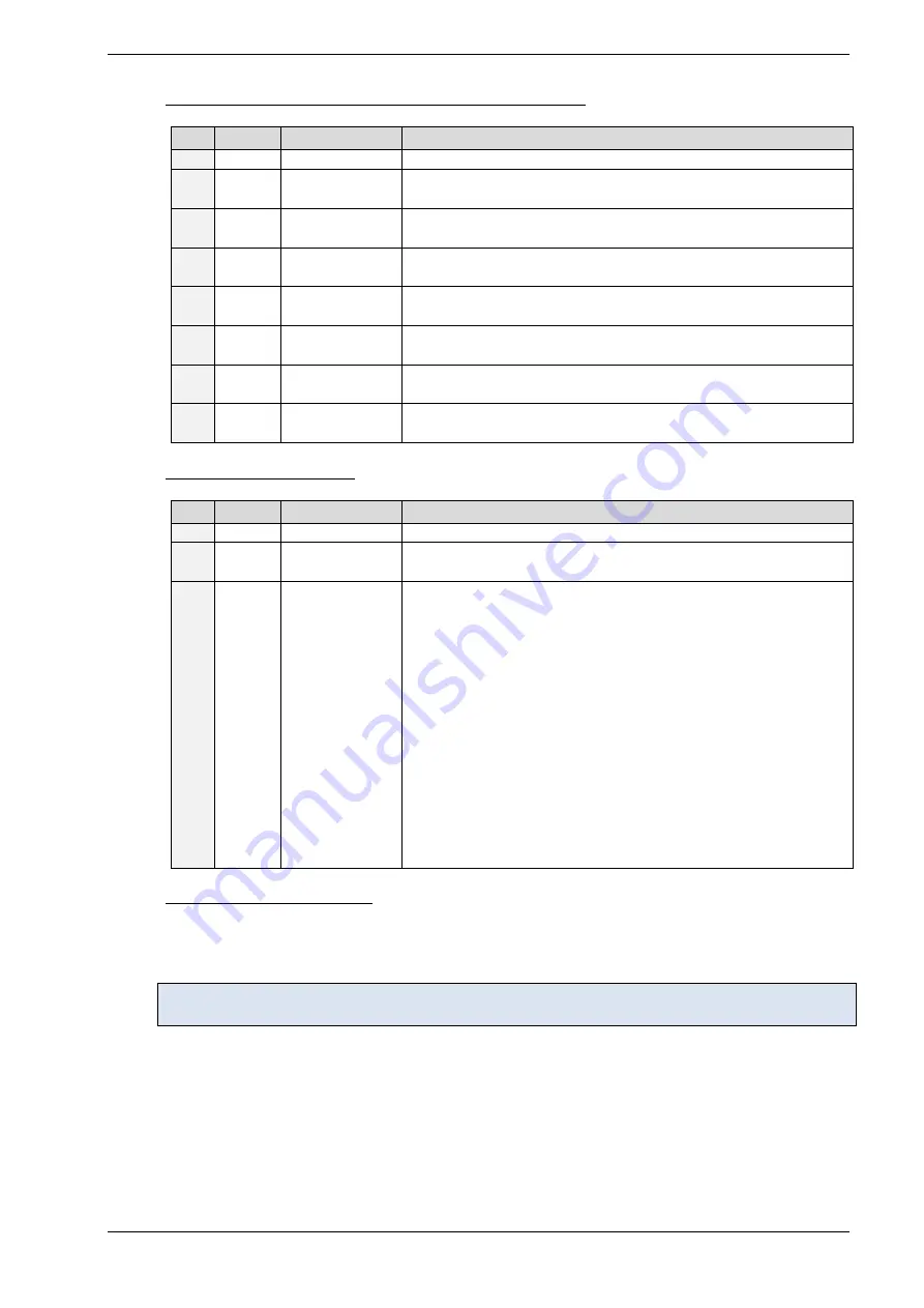
Connect the encoder (
optional - for closed loop operation
)
Pin
Label
Direction
Description
1
GND
Power (GND)
Signal and system ground
2
+5V
Power
(supply output)
+5V output for external circuit
3
A+
Input
Encoder channel A+ input
(differential, non-inverting)
4
A-
Input
Encoder channel A- input
(differential, inverting)
5
B+
Input
Encoder channel B+ input
(differential, non-inverting)
6
B-
Input
Encoder channel B- input
(differential, inverting)
7
N+
Input
Encoder zero / index channel input
(differential, non-inverting)
8
N-
Input
Encoder zero / index channel input
(differential, inverting)
4.
Connect the power supply
Pin
Label
Direction
Description
1
GND
Power (GND)
Common system supply and signal ground
2
V
DRIVER
Power
(supply input)
Stepper driver supply voltage. Without this voltage the stepper
driver and any motor connected will not be energized.
3
V
DIGITAL
Power
(supply input)
Supply voltage for everything else apart from the stepper motor
driver. The on-board voltage regulator generates the necessary
voltages for the digital circuits from this supply. The pin can be
left unconnected. In this case a diode between V
DRIVER
and V
DIGITAL
ensures the supply for the digital parts.
ATTENTION:
The diode has a current rating of 3A. As V
DIGTIAL
is available
at the I/O connectors and at the reference switch connectors
also, always connect this pin to positive supply voltage in
case substantial amount of current is withdrawn from these
pins for external circuits.
It is expected that V
DIGITAL
and V
DRIVER
are connected to the
same power supply output when both pins are used.
Otherwise please ensure that V
DIGITAL
is always equal or
higher than V
DRIVER
when connected (due to the diode).
5.
Switch ON the power supply
Turn power ON. The green LED should be flashing. The motor is powered but in standstill now.
If this does not occur, switch power OFF and check your connections as well as the power supply.
Refer to the hardware manual for further information about the hardware characteristics of your
module!