


Monopack 2 Manual V1.04
7
Copyright © 2010, TRINAMIC Motion Control GmbH & Co. KG
2.3
Stop Switches and Reference Switches
For stop and reference switches, only openers can be used. The stop and reference switch inputs can be used in
different ways:
Two stop switches and a separate reference switch: Connect the left stop switch to the “Stop Switch L”
input and the right stop switch to the “Stop Switch R” input. Connect the reference switch to the “Ref
IN” input.
One stop switch and a separate reference switch: Connect the stop switch to the desired stop switch
input and the other stop switch input permanently to ground.
Combining the reference switch with one stop switch: Connect one switch to the reference switch
input and to the desired stop switch input, as shown in Figure 2.1. If only one stop switch is to be
used connect the other stop switch input to ground.
2.3.1
Linear vs. Circular Drives
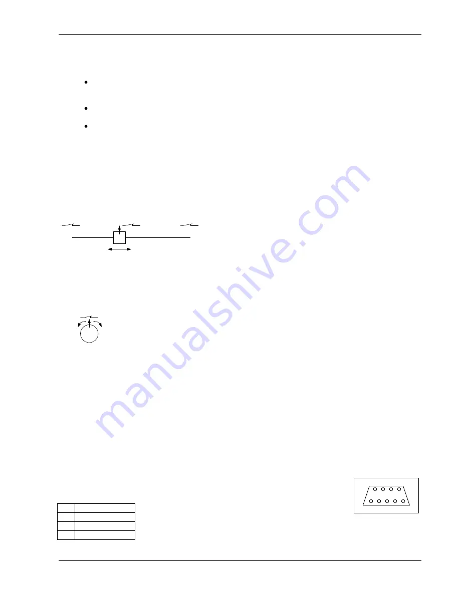
In a linear drive (Figure 2.2), the traveler moves between two end points. It is not necessarily driven by a linear
stepper motor. In most cases, stop switches are used at the end points, and also a reference switch is used for
finding the reference point. The reference switch can also be combined with one of the end switches (as shown in
Figure 2.1).
Right Stop
Switch
Traveller
Left Stop
Switch
Reference
Switch
Negative
Direction
Positive
Direction
Figure 2.2:
A linear drive
In a circular drive (Figure 2.3), the traveler moves around. There are no end points, and for that reason there are
also no stop switches. So the stop switch inputs are disabled in circular mode. A reference switch can be used for
finding the reference point.
Traveller
Reference
Switch
Figure 2.3:
A circular drive
2.4
Incremental Encoder
Connect the two channels of the incremental encoder to the inputs “A” and “B”. An optional null channel can be
connected to the “N” input. The incremental encoder connector also provides a 5V power supply.
2.5
Power Supply
The voltage should be between 12 and 48 Volts to operate and must not exceed 49V. When using a regulated
power supply, set the current limit higher than the maximum motor current.
2.6
The RS232 interface
The 9-pin Sub-D socket provides the RS232 interface. This interface can be used in
Monopack mode as well as in Monopack LT mode. The pin assignments are as follows:
Pin Signal name
2
TxD
3
RxD
5
GND
RS232
1
5
6
9
2=TxD
3=RxD
5=GND