background image


www.trikdis.com 


  13     


May, 2019 


RF transmitter T16


2.


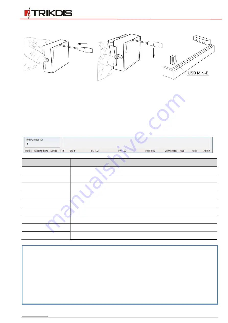
Remove the front cover of the 

T16 

using a flat-head screwdriver as shown below: 


3.


Connect the 

T16 

to a computer using a USB Mini-B cable. 

4.


Launch  the  configuration  program 

TrikdisConfig

.  The  program  will  automatically  recognize  the 

connected  device.  If  required,  enter  the  administrator  or  installer  code  in  a  pop-up  window  and 

TrikdisConfig 

will automatically open the 

T16

 configuration window. 

3.1


Description of TrikdisConfig status bar 

Once the 

T16

 is connected to the 

TrikdisConfig 

software, the program will display information about the 

connected device in the status bar: 


Name 

Description 

Unique ID 

Device’s serial number  

Status 

Operational state 

Device 

Type of device (must show 

T16

SN 

Device’s serial number 

BL 

Bootloader version 

FW 

Device’s firmware version 

HW 

Device’s hardware version 

State 

Type of connection with the program (via USB or remote) 

Administrator 

Access level (shown after access code is approved) 


Note: 

Click 

Read [F4]

 to make the program read and display the settings that are currently saved 

on the device. 
Click 

Write [F5] 

to save the settings made in the program to the device.


Click 

Save [F9]

 to save the settings to a configuration file. You can upload the saved settings 

to  other  devices  later.  This  allows  to  quickly  configure  multiple  devices  with  the  same 

settings. 
Click 

Open [F8]

 and choose a configuration file to view previously saved settings.


If you want to revert to the default settings, click the 

Restore

 button at the lower left of the 

screen. 

Summary of Contents for T16 Series

Page 1: ...www trikdis com UAB Trikdis Draugyst s str 17 LT 51229 Kaunas Lithuania 370 37 408 040 info trikdis lt RF transmitter T16 Installation manual May 2019...

Page 2: ...L S LANDLINE DIALER 11 2 3 SCHEMATICS FOR CONNECTING INPUTS 11 2 4 SCHEMATIC FOR CONNECTING CONTROL PANEL S PGMS 12 2 5 SCHEMATIC FOR CONNECTING A SIREN 12 2 6 SCHEMATICS FOR CONNECTING RS485 MODULES...

Page 3: ...on in order to avoid mistakes that can lead to malfunction or even damage to the equipment Always disconnect the power supply before making any electrical connections Any changes modifications or repa...

Page 4: ...S485 interface for IP transmitters and extension modules 6 inputs selectable types NC NO EOL 2 2 k 1 output 1 1 Description of operation When connected to the terminals of a security control panel the...

Page 5: ...ng a 1 4 antenna it must be vertically oriented and mounted as high as possible Avoid mounting the antenna in places where metal shields or concrete partitions would block the reception antenna The qu...

Page 6: ...ires 1 4 Purpose of terminals Terminal Description DC Power supply terminal 10 15 V DC positive terminal Secondary emissions Meets the requirements of EN 300 113 Broadcasting protocols RAS3 RAS2M LARS...

Page 7: ...input terminal selectable types NC NO EOL 2 2 k factory setting NO IN6 6th input terminal selectable types NC NO EOL 2 2 k factory setting NO OUT1 Output terminal open collector type current up to 1 A...

Page 8: ...hone communicator CID 3 1 4 1 4 2 2300 3 1 4 1 4 2 1400 The zones inputs IN of T16V and T16U transmitters can be connected directly to various devices e g sensors panic button siren output or to the c...

Page 9: ...019 RF transmitter T16 to the keypad bus serial port or cellular communicator on the control panel Avoid mounting the cable in parallel with AC power cables the antenna cable or other strong sources o...

Page 10: ...www trikdis com 10 May 2019 RF transmitter T16...

Page 11: ...DTMF tones Set the automatic message transfer protocol Contact ID If you want to transfer special messages or the panel does not have automatic Contact ID code formatting manually enter the required e...

Page 12: ...after 3 minutes or after using a contact key 2 6 Schematics for connecting RS485 modules When the RS485 data bus is longer than 1 m use a twisted pair cable STP 4x2x0 5 Avoid mounting the cable in pa...

Page 13: ...s serial number Status Operational state Device Type of device must show T16 SN Device s serial number BL Bootloader version FW Device s firmware version HW Device s hardware version State Type of con...

Page 14: ...Enabled tick the box to turn on the transmitter s radio channel RF protocol specify the radio protocol that will be used RAS 2M RAS 3 LARS LARS1 LARS_RAS2M LARS1_RAS2M Account ID enter the user s iden...

Page 15: ...triggered No assign a number to the input Type specify input type NO NC EOL Delay specify input trigger delay time s Event F1 event code sent using the radio transmitter s 1st channel CID code is set...

Page 16: ...l repeater with listen and cancel modes is used o Test periodic test message o Open Close for sending Open Close messages when the TM17 reader is used o Power supply failure power supply failure event...

Page 17: ...t PING messages can only be used for the most important protected objects in a network to avoid a network overload Send PING only if there is no event check the box to send PING signals only when ther...

Page 18: ...nal will be played 3 Hold the key you want to register against the reader The reader s audio signal will switch off The key is now added to the list Remove the key from the reader The green indicator...

Page 19: ...onnecting a siren Blinking LED indicators on the TM17 inform about activated inputs during the time the system is armed When the alarm is disarmed by holding a key to the reader the indicators do not...

Page 20: ...m s control panel are converted to the radio system s RAS2M LARS codes Only Contact ID messages described in the table CID column are converted to the radio system s codes and sent to the ARC The symb...

Page 21: ...fter the update if the box Preserve settings is ticked If the firmware is installed manually it can be changed to a newer or an older version Perform these steps 1 Launch TrikdisConfig 2 Using a USB M...

Reviews: