19
PIPEMASTER™ Model PFM816
92-1412 Rev. 150925
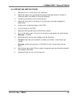
6.2 OPERATING INSTRUCTIONS
1. Measure the I.D. of the pipe to be machined.
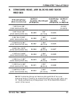
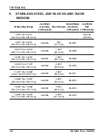
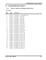
2. Select the right set of Jaw blocks to Clamp in the pipe. Refer to section 8,
Standard Head, Jaw Blocks and Guide Wedges,
3. Install the jaw blocks on the 12 Clamp pins.
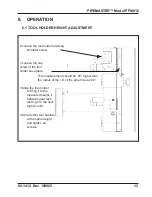
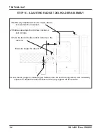
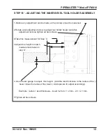
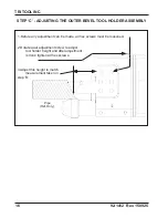
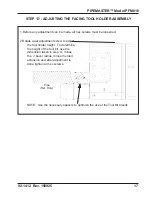
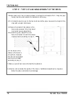
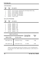
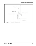
4. Adjust the tool holders according to the previous tool holder adjustment
instructions.
5. Connect the 3 hydraulic hoses to the PFM.
6. Connect power to the HPU.
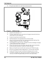
7. Bring the HPU pendant close to the PFM controls.
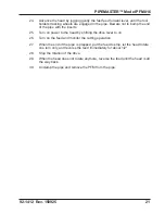
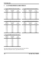
8. Turn on the drive, refer to Fig. 6 and count the head rotation for a full minute.
Example:
72 RPM.
9. Remember this number and multiply it by the feed rate.
•
Formula:
feed rate per revolution x rotation per minute = linear travel per
minute.
•
Example:
0.006” per revolution x 72 RPM = 0.432 ” of linear travel of the
head.
10. Set the feed rate of the PFM by using a magnetic base dial indicator attached
to the back of the PFM.
11. Indicate the end of one of the torque bar.

