background image


49 

Step 5. Using only hand pressure, extend the arbor as far to the right as it will go.  
 
Step 6. Using appropriate GO NO-GO gauges, open the funnel and insert gauges into the 
indenters to determine the "G" dimensions.  
 

NOTE 

Be sure to use gauges corresponding 

to proper wire gauge and contact gauge

 
Step 7. If the "G" dimension 

is 

acceptable, go to Step 14.


If the "G" dimension 

is 

not acceptable, go to Step 8  

 
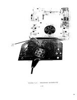
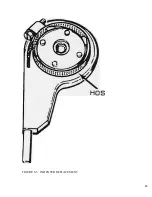
Step 8. Refer to Figure 6-6.  
 
Step 9. Loosen the Stafford clamp collar.  
 
Step 10. Rotate the "ADJUST" adjustable stop counter-clockwise  
to decrease the "G" dimension, or clockwise to increase the "G" dimension.  
 
Step 11. Repeat Steps 5 through 10 until the "G" dimension is within acceptable  

parameters.  

 
Step 12. Hand-tighten the Stafford clamp collar, being careful not to change the  

adjustable stop position.  

 
Step 13. Repeat steps 5 and 6.


NOTE 

Operator-adjustable "G" dimension PORTA-TACs should be adjusted at setting 6. 

If desired after adjustment has been completed, GO NO-GO verification may be 

performed for the remaining settings. 


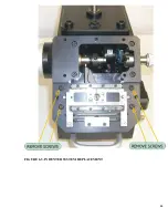
Step 14. Install the crimp cylinder arbor cover plate and the 
 

funnel cover plate removed in Step 3.  

 
Step 15. Connect the air supply to the sleeve valve.  
 
Step 16. Select the magazine with the appropriate contacts and load the magazine onto  

the PORTA-TAC.  

 
Step 17. Set the LAST PART Switch to OFF (up) position  
 

Summary of Contents for PORTA TAC E Series

Page 1: ...E MANUAL PORTA TAC SERIES E MAGAZINE FEED CRIMPER TRI STAR TECHNOLOLGIES 2201 ROSECRANS AVE EL SEGUNDO CA 90245 U S A www tri star technologies com tel 310 536 0444 fax 310 536 9322 SERIAL NUMBER ____________________ VERSION 1 4 ...

Page 2: ...st users in the initial set up verification and operation of the PORTA TAC Crimper It is not intended to be used as the guide to per form major adjustments or to effect major repairs Consult the factory if adjustments or repairs other than those described herein are necessary ...

Page 3: ...ON RESET 14 2 4 NORMAL OPERATION 15 SECTION III INITIAL SET UP Paragraph 3 1 INTRODUCTION 18 3 2 UNPACKING 18 3 3 DROP TUBE AND TRANDFER TIP 19 3 4 PNEUMATIC HOOK UP 20 3 4 5 ELECTRICAL HOOK UP 20 3 5 INITIAL CHECK OUT 20 3 6 FUNCTIONAL CHECK OUT 21 3 7 FUNNEL REPLACEMENT 23 3 8 DROP TUBE TRANSFER TIP REPLACEMENT 23 SECTION IV CRIMP VERIFICATION Paragraph 4 1 INTRODUCTION 24 4 2 INITIAL CRIMP VERI...

Page 4: ...35 SECTION VI MAINTENANCE AND TROUBLESHOOTING Paragraph 6 1 IN T RODUCTION 38 6 2 PREVENTIVE MAINTENANCE 38 6 3 LODGED CONTACT 39 6 4 TRANSFER TIP 39 6 5 TRIGGER 43 6 6 INDENTERS REPLACEMENT 43 6 7 INDENTERS ADJUSTMENT 48 6 8 PNEUMATIC ELECTRIC 52 6 9 TROUBLESHOOTING 52 SECTION VII PARTS LIST 7 1 PARTS LIST 53 ...

Page 5: ...TAC PNEUMATICS 17 4 1 CRIMP CYLINDER ARBOR OPEN 26 4 2 CRIMP CYLINDER ARBOR CLOSED 27 4 3 CRIMP INSPECTION POINTS 30 4 4 IMPROPER CRIMPS 31 4 5 T DIMENSION CHECK POINT 32 5 1 CRIMPS 37 6 1 PANEL COMPONENTS 40 6 2 CABINET COMPONENTS TRANSFER MECHANISM 41 6 3 INDENTER SYSTEM REPLACEMENT 44 6 4 INDENTERS DISENGAGED 45 6 5 INDENTER REPLACEMENT 46 6 6 INDENTER ADJUSTMENT 50 ...

Page 6: ... 11OV 220V electricity available The sealed magazine precludes the loss of loose contacts Figure 1 1 is a photograph o the PORTA TAC It requires no lubrication or preventive maintenance except to periodically change the air filter or drain it Crimp acceptability should be verified in accordance with the user s normal practices Indentors used in the PORTA TAC crimper are qualified to the M22520 spe...

Page 7: ...7 FIGURE 1 1 PORTA TAC CRIMPER FRONT VIEW ...

Page 8: ...8 FIGURE 1 2 PORTA TAC CRIMPER WITH MAGAZINE ...

Page 9: ...9 FIGURE 1 3 PORTA TAC CRIMPER SIDE VIEW ...

Page 10: ... PORTA TAC when the crimp is completed the operator withdraws the conductor with the contact now attached the PORTA TAC re cycles and places another contact in proper position the operator inserts another properly stripped wire into the contact depresses it slightly and the cycle repeats Figure 1 4 shows the funnel through which the operator inserts the conductor into the contact Not all PORTA TAC...

Page 11: ...11 ...

Page 12: ... the feel of the machine within 15 minutes of use Noise generated by the device is minimal operators have been observed to develop a rhythm of insertion and withdrawal based on the unique sounds generated by the device Crimp rates exceeding 1800 crimps per hour have been attained Section V Operating Procedures gives detailed instructions to become familiar with the equipment and operate it correct...

Page 13: ...s properly occurred subsequent events will not occur This design in conjunction with high tolerance machined components reduces significantly the possibility of initiating crimps on incorrect contacts or proceeding to crimp additional contacts if proper crimp tolerances are not being achieved If the crimped contact conductor is not removed after the crimping cycle is complete the PORTA TAC will pa...

Page 14: ...e unless absolutely certain the adjustment is required Indiscriminate changes to regulator or switch settings should not be made A clean air supply is imperative to proper system operation Filter F l should be drained or changed as required 2 3 INITIAL TURN ON RESET Set the LAST PART Switch to the OFF up position Reset occurs any time the operator controlled sleeve valve is initially closed or ope...

Page 15: ...at the Crimp Head Forward sensor G Sensor and allow air pressure to be applied to S 4 the system will terminate its cycle until reset The purpose of this feature is to insure the Crimp Cylinder has advanced to correspond to the G dimension set Supply for G Sensor Air Bleed is provided by R 4 If the Crimp Cylinder has traveled far enough to block the air bleed at the G Sensor sufficient air pressur...

Page 16: ...n the Transfer Tip adequate vacuum will exist to switch on the Transfer Tip Sensor S 6 Supply for Vacuum Sensor switch is provided by Vacuum Generator VG l Note If a contact does not seat properly in the Transfer Tip the cycle will terminate until reset With S 6 turned on again V 2 is turned off allowing the Transfer Arm to return to the ready to crimp position The PORTA TAC is now ready to have a...

Page 17: ...17 ...

Page 18: ...The time required to have this PORTA TAC ready for Crimp Verification Section IV is less than thirty minutes 3 2 UNPACKING The shipping container in which the PORTA TAC is transported is constructed to ensure safe arrival of the device Perform the following steps to unpack the PORTA TAC Step 1 Carefully open the container and remove all packing material NOTE Be certain to discard only packing mate...

Page 19: ...ary to change the drop tube or the transfer tip or both for a different contact Perform the following steps to install a drop tube or transfer tip Step 1 Unlock and open the hinged panel located on the right side of the PORTA TAC Very carefully remove all packaging material Step 2 Refer to Figure 6 2 Observe if the drop tube is installed If not obtain the appropriate drop tube and install by inser...

Page 20: ...CP21 Plug or FOSTER 3103 Quick Disconnect with 10 3 Plug NOTE The air supply must be 15 CFM at 85 PSIG through a 3 8 ID hose or conduit A Quick Disconnect Hose Fitting is RECOMMENDED as some procedures require the air source be DISCONNECTED COMPLETELY from the PORTA TAC Step 3 Install the air fitting CAUTIQN Do not close the sleeve valve at this time 3 4 5 ELECTRICAL HOOK UP Plug in power pack 110...

Page 21: ...he following readings DO not adjust any regulators Gauge for R l 60 Psi Gauge for R 2 Approx 20 Psi If regulator readings are satisfactory disconnect the air supply by disengaging the sleeve valve Proceed to Section 3 6 Functional Check Out 3 6 FUNCTIONAL CHECK OUT The purpose of this initial functional check out of the PORTA TAC is to ascertain that the operation of the device satisfactory In par...

Page 22: ... valve Step 5 Open the funnel and observe if a contact is present No contact should be present in the transfer tip Close the funnel Step 6 Momentarily depress the initial part PUSHBUTTON switch The PORTA TAC will now cycle Step 7 Open the funnel and observe that a contact is present Using tweezers remove the contact Close funnel Step 8 Repeat Steps 6 through 8 until satisfied that magazine belt ad...

Page 23: ...nnel cover plate Step 4 Remove the 2 each screws from each of the funnel halves Step 5 Remove the funnel halves Step 6 Install the new funnel halves using the screws removed in the Step 4 NOTE Either funnel half may be used in either position as they are self aligning 3 7 DROP TUBE TRANSFER TIP REPLACEMENT If it is necessary to change or replace the drop tube or transfer tip after initial set up r...

Page 24: ...stablished to verify acceptable crimps 4 2 INITIAL CRIMP VERIFICATION The Initial Crimp Verification should be performed immediately after the PORTA TAC has been set up Section II Although the procedure is the same as all other verification tests it affords the user an opportunity to record data before the machine has been used extensively Read and understand Section V Operating Procedures before ...

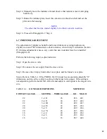
Page 25: ...NTACT GG SETTING WIRE GAUGE GO NO GO 22 1 or I 26 016 021 22 2 or II 24 019 024 22 3 or III 22 022 027 20 4 or IV 24 025 030 20 5 or V 22 029 034 20 6 or VI 20 033 038 or 16 1 or 4 20 029 034 16 2 or 5 18 033 038 16 3 or 6 16 037 042 Step 6 Using only hand pressure extend the arbor as far to the right as it will go Step 7 Using GO and NO GO gauges open the funnel and insert gauges into the indente...

Page 26: ...26 FIGURE 4 1 CRIMP CYLINDER ARBOR OPEN ARBOR COVER PLATE REMOVED ...

Page 27: ...27 FIGURE 4 1 CRIMP CYLINDER ARBOR CLOSED ARBOR COVER PLATE REMOVED ...

Page 28: ...n the funnel and observe if a contact is present NOTE No contact should be present in the transfer tip Close the funnel Step 16 Momentarily depress the INITIAL PART pushbutton switch Step 17 Open the funnel and observe that a contact is present Let the funnel close NOTE The funnel should be closed during normal operation when inserting a conductor Step 18 Using a conductor of proper material and g...

Page 29: ...he transfer tip Step 22 Inspect the crimp per required specifications Step 23 Figures 4 3 through 4 5 are samples of inspection criteria Step 24 Repeat Steps 12 through 22 for each conductor wire gauge to obtain necessary specimens inspect per established procedure NOTE Immediately prior to the last crimp of a given contact being made set the LAST PART Switch to the ON down position Step 25 Open t...

Page 30: ...30 FIGURE 4 3 CRIMP INSPECTION POINTS ...

Page 31: ...31 FIGURE 4 4 IMPROPER CRIMPS ...

Page 32: ...32 ...

Page 33: ...ctions III and IV Read this section completely before operating the PORTA TAC WARNING DO NOT ATTEMPT TO CRIMP ANY FOREIGN SUBSTANCES MACHINE DAMAGE WILL RESULT 5 2 NORMAL OPERATION Perform the following steps to operate the PORTA TAC Step1 Transport the PORTA TAC to the work area where crimping is to be performed NOTE Lift and transport the PORTA TAC using only the handles Step2 Select the magazin...

Page 34: ...conductor Step 9 Obtain a properly stripped conductor or coil of properly stripped conductors Select the proper G dimension setting if applicable See Table 5 1 TABLE 5 1 EXTERNAL G SELECTIONS SETTING WIRE SIZE For 22 gauge contacts 1 or I 26 gauge 2 or II 24 gauge 3 or III 22 gauge For 20 gauge contacts 4 or IV 24 gauge 5 or V 22 gauge 6 or VI 20 gauge For 16 gauge contacts 1 or 4 20 gauge 2 or 5 ...

Page 35: ...ct the proper G dimension setting if wire gauges change NOTE Periodically observe the magazine belt to determine if enough contacts are present A different colored carrier approaching the drop tube is an indication that the magazine belt is almost empty Step 15 Immediately prior to the last crimp being made the LAST PART Switch to ON down position Step 16 Perform the last crimp Step l7 Open the sl...

Page 36: ...or need observe are 1 Do not insert a conductor so fast as force conductor strands to spring back out the contact 2 Remove the crimped conductor only when the crimp cycle is complete funnel open 3 Be certain the magazine is filled on with the proper type contacts ...

Page 37: ...37 CONDUCTOR STARNDS PROPER INDENTS VISIBLE ACCEPTABLE CRIMP BIRDCAGE UNACCEPTABLE CRIMP FIGURE 5 1 CRIMPS ...

Page 38: ...should e drained by placing a cup or other container under Fl opening the Fl drain and draining the filter NOTE DO not allow the moisture to spray drip or enter the cabinet when draining The vacuum filter RFV l can easily be located in line between the transfer tip holder and the PORTA TAC Control Unit If the vacuum filter becomes clogged decreased performance with part detection at the transfer t...

Page 39: ...a contact lodges itself in the drop tube perform the following steps WARNING BE CERTAIN THE AIR SUPPLY HAS BEEN TURNED OFF Step 1 Remove magazine from PQRTA TAC Crimper Step 2 Remove drop tube and dislodge jammed contact Step 3 Install magazine and drop tube Step 4 Turn air on again and verify proper contact feed 6 4 TRANSFER TIP The transfer tip is equipped with a vacuum sensing system that preve...

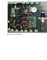
Page 40: ...40 FIGURE 6 1 PANEL COMPONENTS ...

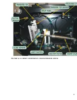
Page 41: ...41 FIGURE 6 2 CABINET COMPONENTS TRANSFER MECHANISM ...

Page 42: ...oper transfer tip verify transfer tip sensor 8 6 is operational by performing the following A Turn air off B Remove contact from transfer tip C Remove Power Pack from outlet D Remove control unit cover E Turn air on F Locate 8 6 and vacuum line G Fully pinch vacuum line repeatedly and verify if 8 6 is switching on and off An audible click should be heard from the switch each time it is activated P...

Page 43: ...f B Remove transfer Tip C Remove power pack from outlet D Remove control unit cover E Turn air on F Locate 8 1 and slide sensor line G Fully pinch slide sensor line repeatedly and verify if 8 1 is switching on and off An audible click should be heard from switch each time it is activated Please note Should the work environment be too noisy for an effective audible check an electrical meter may be ...

Page 44: ...44 FIGURE 6 3 INDENTER SYSTEM REPLACEMENT ...

Page 45: ...45 ...

Page 46: ...46 FIGURE 6 5 INDENTER REPLACEMENT ...

Page 47: ...lly lift the indenter plate up from the housing such that the Cam arm disengages smoothly from the arbor shaft It may be necessary to manually move the arbor shaft to the right Step 9 Carefully turn the indenter plate over exposing the indenter came CAUTION Do not pinch the air line Step 10 Refer to Figure 6 5 Step 11 Carefully remove the indenter cam arm Step 12 Observe indenter orientation and r...

Page 48: ...been installed Paragraph 6 6 Perform the following steps to adjust indenters Step 1 Open the sleeve valve Step 2 Disconnect the air supply from the sleeve valve Step 3 Remove the crimp cylinder arbor cover plate and the funnel cover plate Step 4 Refer to Table 6 1 If the PORTA TAC Crimper has an operator adjustable G dimension control set the control to setting 6 the largest wire gauge If the sett...

Page 49: ... clockwise to increase the G dimension Step 11 Repeat Steps 5 through 10 until the G dimension is within acceptable parameters Step 12 Hand tighten the Stafford clamp collar being careful not to change the adjustable stop position Step 13 Repeat steps 5 and 6 NOTE Operator adjustable G dimension PORTA TACs should be adjusted at setting 6 If desired after adjustment has been completed GO NO GO veri...

Page 50: ...50 ...

Page 51: ... all conductor strands enter the funnel without bending back insert the conductor into the funnel until it bottoms out Step 24 When the conductor bottoms out initiate the crimp cycle will Step 25 When the crimping cycle is complete the funnel will open at this time remove the conductor NOTE When the funnel opens remove the conductor smoothly by simply pulling it towards yourself Step 26 Inspect th...

Page 52: ...in magazine l b Drop tube jammed l c Incorrect contacts l d Incorrect drop tube I e Incorrect transfer tip l f Magazine not aligned or jammed l g Last part switch is on down l h Transfer arm improperly align 2 Contact in transfer tip appears seated but transfer arm remains in vertical position 2 a Bent contact 2 b Contact has rough shoulder 2 c Vacuum circuit leaking 2 d 8 6 improperly adjusted 3 ...

Page 53: ...53 ...
Reviews: