48
Step 14. Manually move the indenter arm and observe that indenters move' and spring
back freely.
Step 15. Rotate the indenter plate, insert the cam arm into the arbor shaft and set the
plate onto the housing.
NOTE
The arbor shaft can be rotated slightly to facilitate cam arm insertion.
Step 16. Proceed to Paragraph 6-7, Step 4.
6-7 INDENTERS-ADJUSTMENT
The adjustment of indenters should be performed whenever existing indenters are
slightly worn and
"G"
dimension is out-of-tolerance, when Crimp Verification (Section
IV) dictates adjustment is neces- sary, and when new indenters have been installed
(Paragraph 6-6).
Perform the following steps to adjust indenters:
Step 1. Open the sleeve valve
Step 2. Disconnect the
air
supply from the sleeve valve
Step 3. Remove the crimp cylinder arbor cover plate and the funnel cover plate.
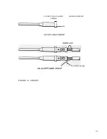
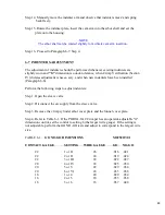
Step 4. Refer to Table 6-1. If the PORTA-TAC Crimper has an operator-adjustable "G"
dimension control, set the control to setting 6 (the largest wire gauge). If the setting is
not adjustable, perform the GO NO-GO tests and adjust to correspond to the largest wire
size.
TABLE 6-1.
GO NO-GO DIMENSIONS
M22520/7-01
CONTACT GAUGE
SETTING
WIRE GAUGE
GO
NO-GO
22
1 or II
26
.016
.021
22
2 or II
24
.019
.024
22
3 or III
22
.022
.027
20
4 or IV
24
.025
.030
20
5 or V
22
.029
.034
20
6 or VI
20
.033
.038
16
1 or 4
20
.029
.034
16
2 or 5
18
.033
.038
16
3 or 6
16
.037
.042
Summary of Contents for PORTA TAC E Series
Page 7: ...7 FIGURE 1 1 PORTA TAC CRIMPER FRONT VIEW ...
Page 8: ...8 FIGURE 1 2 PORTA TAC CRIMPER WITH MAGAZINE ...
Page 9: ...9 FIGURE 1 3 PORTA TAC CRIMPER SIDE VIEW ...
Page 11: ...11 ...
Page 17: ...17 ...
Page 26: ...26 FIGURE 4 1 CRIMP CYLINDER ARBOR OPEN ARBOR COVER PLATE REMOVED ...
Page 27: ...27 FIGURE 4 1 CRIMP CYLINDER ARBOR CLOSED ARBOR COVER PLATE REMOVED ...
Page 30: ...30 FIGURE 4 3 CRIMP INSPECTION POINTS ...
Page 31: ...31 FIGURE 4 4 IMPROPER CRIMPS ...
Page 32: ...32 ...
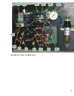
Page 40: ...40 FIGURE 6 1 PANEL COMPONENTS ...
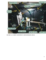
Page 41: ...41 FIGURE 6 2 CABINET COMPONENTS TRANSFER MECHANISM ...
Page 44: ...44 FIGURE 6 3 INDENTER SYSTEM REPLACEMENT ...
Page 45: ...45 ...
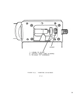
Page 46: ...46 FIGURE 6 5 INDENTER REPLACEMENT ...
Page 50: ...50 ...
Page 53: ...53 ...

