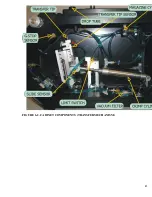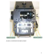
34
5-2 NORMAL OPERATION (CONT.)
Step 4
.
Set the LAST PART Switch to the QFF position (up)..
Step 5. Close the sleeve valve.
Step 6. Open the funnel and observe if a contact is present.
NOTE
No contact should be present in the transfer tip.
Step 7. Depress the INITIAL PART pushbutton switch until the PORTA-TAC cycles.
Step 8. Open the funnel and observe that a contact is present. Let the funnel close.
NOTE
The funnel should be closed during normal operation when inserting a conductor.
Step 9. Obtain a properly stripped conductor or
coil
of properly stripped
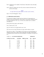
conductors. Select the proper "G" dimension setting (if applicable).
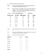
See Table
5-1.
TABLE 5-1. .
EXTERNAL "G" SELECTIONS
SETTING
#
WIRE SIZE
#
For
22 gauge
contacts:
1 or I
26 gauge
2 or II
24 gauge
3 or III
22 gauge
For
20 gauge
contacts:
4 or IV
24 gauge
5 or V
22 gauge
6 or VI
20 gauge
For
16 gauge
contacts:
1 or 4
20 gauge
2 or 5
18 gauge
3 or 6
16 gauge
Step 10. Carefully and smoothly insert a conductor into the funnel, being careful all
conductor strands enter the funnel.
NOTE
Conductor strands do not have to be twisted together,
but they do have to enter the funnel parallel to one another
.
Summary of Contents for PORTA TAC E Series
Page 7: ...7 FIGURE 1 1 PORTA TAC CRIMPER FRONT VIEW ...
Page 8: ...8 FIGURE 1 2 PORTA TAC CRIMPER WITH MAGAZINE ...
Page 9: ...9 FIGURE 1 3 PORTA TAC CRIMPER SIDE VIEW ...
Page 11: ...11 ...
Page 17: ...17 ...
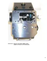
Page 26: ...26 FIGURE 4 1 CRIMP CYLINDER ARBOR OPEN ARBOR COVER PLATE REMOVED ...
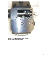
Page 27: ...27 FIGURE 4 1 CRIMP CYLINDER ARBOR CLOSED ARBOR COVER PLATE REMOVED ...
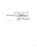
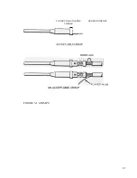
Page 30: ...30 FIGURE 4 3 CRIMP INSPECTION POINTS ...
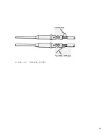
Page 31: ...31 FIGURE 4 4 IMPROPER CRIMPS ...
Page 32: ...32 ...
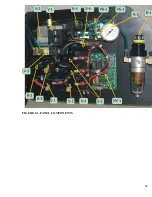
Page 40: ...40 FIGURE 6 1 PANEL COMPONENTS ...
Page 41: ...41 FIGURE 6 2 CABINET COMPONENTS TRANSFER MECHANISM ...
Page 44: ...44 FIGURE 6 3 INDENTER SYSTEM REPLACEMENT ...
Page 45: ...45 ...
Page 46: ...46 FIGURE 6 5 INDENTER REPLACEMENT ...
Page 50: ...50 ...
Page 53: ...53 ...


