15
2-4
NORMAL OPERATION
This discussion originally assumes a contact is in the Transfer Tip after Initial Turn-
On.
When a properly stripped conductor is inserted into the wire funnel and subsequently
into the contact, it eventually bottoms out in the contact. Continued pressure depresses
the trigger mechanism until Nl Slide Sensor closes, which blocks the air bleed existing
at the Nl Sensor. When this air bleed is closed, sufficient air pressure exists to switch
S-l. Supply for this air bleed is provided by R-3.
Immediately upon the switching on of 8-1, the controller energizes the solenoid at V-I.
With V-I activated, air pressure is supplied to the extend portion of the Crimp Cylinder
(CR-l) initiating the crimp cycle.
Note: this event is precluded from happening if no part exists in the transfer tip.
The mechanics bf the Crimp Cylinder are such that, unless the cylinder moves (closes)
enough to block the air bleed at the Crimp Head Forward sensor (G Sensor) and allow
air pressure to be applied to S-4, the system will terminate its cycle until reset. The
purpose of this feature is to insure the Crimp Cylinder has advanced to correspond to
the "G" dimension set.
Supply for "G" Sensor Air Bleed is provided by R-4.
If the Crimp Cylinder has traveled far enough to block the air bleed at the "G" Sensor,
sufficient air pressure will exist to change the state of S-4.
As soon as S-4 is switched on, the controller energizes the solenoid at V-3. Turning on
V-3 turns off air pressure to the slide cylinder and turns on air pressure to the Wire
Funnel Cylinders (FC-I). It is at this point in the cycle that the operator removes the
crimped contact/conductor.
With no contact now in the transfer tip, Vacuum Sensor Switch S-6 is turned off. With
S-6 off, the controller energizes V-2 sending the Transfer Arm (TA-I) to the vertical
(pick-up) position.
Note: In proper operating order, the Transfer
Arm will never retract with a contact present in the Transfer tip. This feature prevents
the possibility of dropping a contact into an already loaded transfer tip.
Summary of Contents for PORTA TAC E Series
Page 7: ...7 FIGURE 1 1 PORTA TAC CRIMPER FRONT VIEW ...
Page 8: ...8 FIGURE 1 2 PORTA TAC CRIMPER WITH MAGAZINE ...
Page 9: ...9 FIGURE 1 3 PORTA TAC CRIMPER SIDE VIEW ...
Page 11: ...11 ...
Page 17: ...17 ...
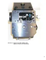
Page 26: ...26 FIGURE 4 1 CRIMP CYLINDER ARBOR OPEN ARBOR COVER PLATE REMOVED ...
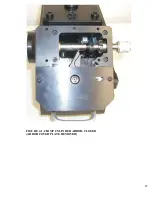
Page 27: ...27 FIGURE 4 1 CRIMP CYLINDER ARBOR CLOSED ARBOR COVER PLATE REMOVED ...
Page 30: ...30 FIGURE 4 3 CRIMP INSPECTION POINTS ...
Page 31: ...31 FIGURE 4 4 IMPROPER CRIMPS ...
Page 32: ...32 ...
Page 40: ...40 FIGURE 6 1 PANEL COMPONENTS ...
Page 41: ...41 FIGURE 6 2 CABINET COMPONENTS TRANSFER MECHANISM ...
Page 44: ...44 FIGURE 6 3 INDENTER SYSTEM REPLACEMENT ...
Page 45: ...45 ...
Page 46: ...46 FIGURE 6 5 INDENTER REPLACEMENT ...
Page 50: ...50 ...
Page 53: ...53 ...


