Trenton ESP+ Operating Instructions Manual Download Page 9

CONNECT BY WIFI SERVICE TOOL

therm

solutions

ENTER

BACK

®

Efficiency

Evaporator


Press and hold for 

manual defrost

24-hour 

Emergency Technical Support

1.888.337.3358

therm

solutions

PWR

WIFI

LAN

WAN

3G/4G

LAN Port

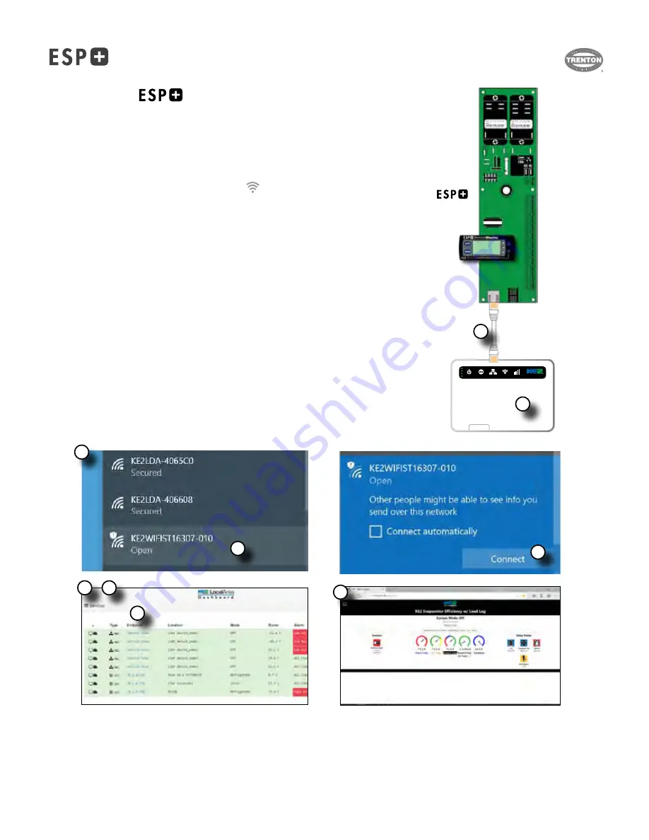
1. Using the RJ-45 cable (included with the KE2 WiFi Service Tool), 

connect the KE2 WiFi Service Tool to the ESP+ controller.

2. Using the power button, 

turn ON the service tool

.

3. 

Connect to the KE2 WIFI Service Tool

  If using a computer, click the wireless connection icon 

  typically found in the bottom right hand corner of the computer screen. 

  It will open a small window with a list of available networks. 

  If using a mobile device, open the WIFI network settings to see available networks.

  There are 2 wireless networks available: 


a.  KE2WIFIST-... : wireless network is Open, and no password is required.


b.  KE2LDA-... :wireless network is Secure, and requires the password 


provided on the label.


4. 

Select the KE2WIFIST wireless network

.

5. Click 

Connect

.

6.  Once connected to the device, 

launch the browser of your preference

  i.e. Google Chrome, Mozilla Firefox, Apple Safari etc.

7. 

Navigate to one of the following addresses, 192.168.50.1 or https://ke2lda

  A list of all available connected controllers will be shown.


8. 

Click on the controller you would like to view.

9. The 

browser will display the controller’s home screen

 (MasterView).  

Connecting The 

 To The Optional KE2 WiFi Service Tool


Controller

8

7

5

4

3

6

2

1

9

T30-ESP-OM--1

11/09/20

- 9 -

Summary of Contents for ESP+

Page 1: ...Support Resources 2 3 3 6 7 8 9 10 11 12 14 15 17 BACK Intuitive Evaporator Control Technology Bulletin T30 ESP OM 2 1 Part 1107522 OPERATING INSTRUCTIONS PRODUCT SUPPORT web www t rp com esp email e...

Page 2: ...default view Manual Valve Control Press and hold the BACK button arrow to put the EEV in Manual Control mode and arrows will control the valve opening ENTER will advance to the next digit and BACK wi...

Page 3: ...ULT DESCRIPTION tS tS ROOM TEMP Room Temp Setpoint 50 0 F 90 0 F 10 F or 35 F Walk in freezer 10 F or cooler 35 F room temp to be main tained rFG rF REFRIGERANT Refrigerant N A N A R 404A Type of refr...

Page 4: ...or The amount of time in minutes before an alarm condition is initiated if door is open room temperature is 5 degrees above ROOM TEMP AIR TEMP DIFF AU1 AU1 AUX IN 1 MODE Aux Input 1 mode N A N A Coil...

Page 5: ...vap Defrost Synchronized or Independent Synchronized Synchronized synchronize bonded controller in defrost mode Inde pendent bonded controllers defrost independently MULTI EVAP SENSOR Multi Evap Senso...

Page 6: ...umber of times to maintain suction pressure LPA LPA LOW PRESSURE Low Pressure Alarm Suction pressure dropped below expected point excessive number of times PrF PrF N A Process Failure Basic Display is...

Page 7: ...List sticker on the inside of the access panel of the evaporator 5 On a computer connected to the same network as your ESP controller open any browser Chrome Firefox Edge etc 6 Enter the ESP controll...

Page 8: ...iP1 5 Record the four IP iP1 iP2 iP3 iP4 values a Use the and arrows to find iP1 iP1 c Press and release the ENTER button to display the current setting d Record this number e Press the BACK button f...

Page 9: ...If using a mobile device open the WIFI network settings to see available networks There are 2 wireless networks available a KE2WIFIST wireless network is Open and no password is required b KE2LDA wir...

Page 10: ...Select submit or press enter on your keyboard 7 Click Discover The IP addresses of the available controllers will populate Click OK if prompted by browser to confirm 8 Type 1 in the Bond State area of...

Page 11: ...method is used to control the temperature 16 Click Save to save the settings 17 The second controller and subsequent controllers must be configured to match the Multi settings of the first controller...

Page 12: ...SAMPLE WIRING DIAGRAM 208 230 1 60 AIR DEFROST MODELS w SAMPLE ONLY Refer to Product Data and Installation for details specific to your unit SAM PLE O N LY T30 ESP OM 1 11 09 20 12...

Page 13: ...SAMPLE WIRING DIAGRAM 208 230 1 60 ELECTRIC DEFROST MODELS w SAMPLE ONLY Refer to Product Data and Installation for details specific to your unit SAM PLE O N LY T30 ESP OM 1 11 09 20 13...

Page 14: ...CLo Closed Setpoint Option for Aux Input State A1A A2A A3A setpoints Input will be Active when it reads a closed circuit CLt CLt Coil Temp Variables Coil temperature TCoil Sensor as measured by the co...

Page 15: ...drops on the walk in s surfaces Fir Fir Firmware Version Variables Current version of the firmware on the controller FoC FoC Fans on with Compressor Setpoint Option under Refrig Fan Type rFt setpoint...

Page 16: ...by the Auxiliary Input SA SA KE2 Smart Access Setpoint Turn KE2 Smart Access on or off EnA enable KE2 Smart Access diS disable KE2 Smart Access SAt SAt Saturation Temp Variables Saturation temperature...

Page 17: ...NOTES T30 ESP OM 1 11 09 20 17...

Page 18: ...NOTES T30 ESP OM 1 11 09 20 18...

Page 19: ...PRODUCT SUPPORT RESOURCES Visit www t rp com esp for product information manuals FAQ and more T30 ESP OM 1 11 09 20 19...

Page 20: ...com call 1 844 893 3222 x501 email shipping t rp com call 1 844 893 3222 x503 web www t rp com warranty email warranty t rp com call 1 844 893 3222 x507 Due to the manufacturer s policy of continuous...

Reviews: