


QUICK START LAN SETUP
(cont'd)
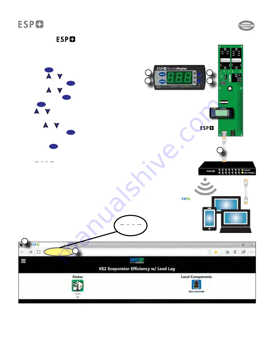
1.
Connect Ethernet (Cat5) cable to the ESP+ controller and to an open port on a network switc
h.
2. Use the on-board display to
enable DHCP setpoint.
a. Hold the
BACK
button for 3 seconds to access the set point menu.
b. Use the
and
arrows to find the
dHC
setpoint.
c. Press and release the
ENTER
button to display the current setting.
d. Use the
and
arrows to Enable (
EnA
).
e. Press and hold the
ENTER
button for 3 seconds to confirm the setting and Enable DHCP.
3. Press the
BACK
button a few times to
return to the default display.
4. Use the
and
arrows to
scroll through the controller variables until the IP settings are found.
(
iP1
)
5.
Record the four IP
(
iP1
,
iP2
,
iP3
,
iP4
)
values
:
a. Use the
and
arrows to find iP1 (
iP1
)
c. Press and release the
ENTER
button to display the current setting.
d. Record this number.
e. Press the
BACK
button.
f. Repeat for iP2 (
iP2
), iP3 (
iP3
) and iP4 (
iP4
),
IP =
10 . 0 . 0 . 12
(Example)
iP1 iP2 iP3 iP4
6.
On a computer connected to the same network, open any browser
(Chrome, Firefox, Edge etc.).
7.
Enter the
ESP+ controller IP Address
(from step 5 above)
into the address bar of the browser
and press enter.
The controller Home page should be displayed.
If the controller webpage does not load, additional setup support or IT support may be required
Connecting The
To A LAN (Local Area Network)
(IP Address Sticker NOT Available)
Controller
Ethernet
(Cat5)
Cable
Network / Router
10 . 0 . 0 . 12
(Example)
10.0.0.12
/index.htm
1
2
3
4
5
6
7
ESP+ Dashboard
ESP+ Dashboard
T30-ESP-OM--1
11/09/20
- 8 -
Summary of Contents for ESP+
Page 17: ...NOTES T30 ESP OM 1 11 09 20 17...
Page 18: ...NOTES T30 ESP OM 1 11 09 20 18...


