


User Interface
This display uses a familiar menu structure to allow service technicians to
change the major setpoints. The setpoints may also be accessed using the
controller’s webpages.
Variables Menu
The
and
arrows move the user through the available options for the Vari-
ables Menu. If alarms are present, they will be displayed and can be viewed using
the up and down arrows.
Basic Menu
Pressing and holding the
ENTER
button enters the
Basic Setpoints
menu. See
page 3 for details.
Advanced Menu
Pressing and holding the
BACK
button enters the
Advanced Setpoints
menu. See
page 3 for details
The
ENTER
button is used to save an input option when it has been changed.
The
ENTER
button must be held for 3 seconds, to prevent accidental changes.
Changes may be discarded by waiting, to allow the controller to time-out and
return to default screen, or by pressing the
BACK
button.
The
BACK
button is
used to return to the previous screen. Pressing the
BACK
button several times
will return the controller to the default view.
Additional Setpoints
For the majority of users, the Basic Display will provide the necessary parameters
to setup the controller.
From the default display, pressing the
and
arrows will cycle through the
Variables
menu. The
ENTER
button will toggle between the variable name and
value.
Changing Setpoints
Pressing and holding the
ENTER
button will enter the
Basic Setpoints
menu. Press
ENTER
button to toggle between setpoint and value.
Pressing and holding the
BACK
button will enter the
Advanced Setpoints
menu.
Press
ENTER
button to toggle between setpoint and value.
When the parameter value is displayed it may be changed by using
and
arrows, and
ENTER
buttons. The
and
arrows will increase or decrease nu-
merical values, and will scroll through the available options, on the non-numerical
setpoints.
Press and hold the
ENTER
button for 3 seconds to save the displayed value.
To abort changes, press the
BACK
button to return to the default view
Manual Valve Control
Press and hold the
BACK
button &
arrow to put the EEV in
Manual Control
mode.
and
arrows will control the valve opening.
ENTER
will advance to
the next digit, and
BACK
will exit this mode.
Manual Defrost
Press and hold
ENTER
and
to put the controller into
Defrost
. The defrost will
terminate automatically based on coil temperature, however, pressing and holding
ENTER
and
again during defrost will skip to drain (drip) mode.
Note: Fans may run for the first few minutes of electric defrost before fans
turn off and heaters are energized
.
System Off (Pumpdown)
Press and hold
BACK
and
at the same until SoF is displayed. The controller
is in system off and will not refrigerate or defrost until system off is cleared or
one hour has passed. Press and hold
BACK
and
again to exit system off.
Display Lock
Press and hold
BACK
and
ENTER
at the same until
LoC
is displayed. The display
will be locked and show
LoC
whenever a button is pressed. To unlock, press and
hold
BACK
and
ENTER
until
LoC
dissapears.
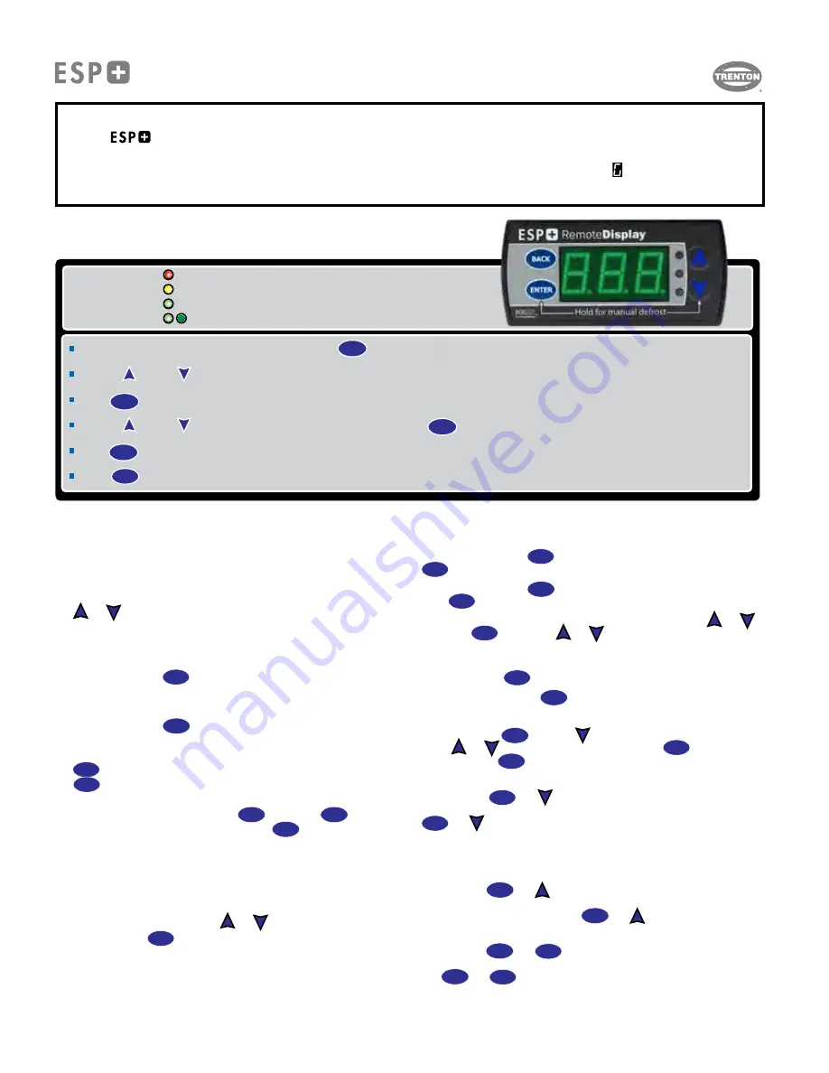
Access Setpoint mode by pressing and holding the button until tS (temperature setpoint) displays on the screen
ENTER
Use the up and down arrows to scroll through the available setpoints.
ENTER
Press to view the current setting.
Indicator lights
Red light - critical Alarm (system not running)
Yellow light - non-critical alarm (system running)
Green light - compressor on
Green flashing - compressor waiting on timer to start/stop
Use the up and down arrows to change the setpoint.
ENTER
Press to move between the digits to accelerate the changes.
ENTER
Press and hold to confirm each setpoint change.
BACK
Press to escape.
Navigation Using the Basic Display
BASIC DISPLAY / USER INTERFACE
IMPORTANT NOTE:
Your
Intuitive Evaporator Control is pre-programmed (with the exception of bonding multiple controllers paired with
a single condensing unit) at the factory and will begin operating as soon as power is applied using the following
default settings : ROOM TEMP (
tS
) = -10 °F (freezer) or 35 °F (cooler), REFRIGERANT (
rF
) = R-404A,
DEFROST TYPE (
dtY
) = Defrost Type (Air or Electric).
Use this manual to make any adjustments you require.
ts
T30-ESP-OM--1
11/09/20
- 2 -
Summary of Contents for ESP+
Page 17: ...NOTES T30 ESP OM 1 11 09 20 17...
Page 18: ...NOTES T30 ESP OM 1 11 09 20 18...


