background image

TV-IP612P/WN (Wireless N) Pan/Tilt/Zoom Internet Camera


78


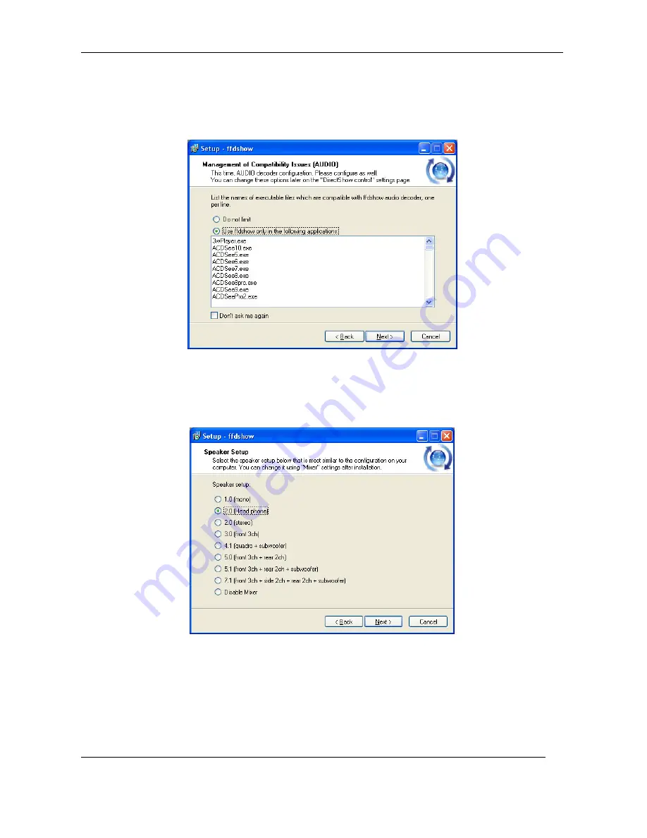
9.  Click to check the audio applications that use ffdshow. For IPCamPlayer it is only 

necessary to use the default applications already selected. Click 

Next

 to continue. 


10. Choose a speaker setup or choose Disable mixer if unsure. The audio function will work 

regardless of what speaker setup is chosen. Usually it will choose the default arrangement 
used on system on which it is being installed. Click 

Next

 to continue. 


11. Review the information and click 

Install

 if satisfied that it is correct to install the necessary 

codecs. The installation will take a few seconds. 


Summary of Contents for TV-IP612P

Page 1: ......

Page 2: ...amera 11 SECURITY 12 APPLICATION 13 USING THE UTILITY 14 SetupWizard 14 USING THE CAMERA WEB MANAGER 30 Accessing the Camera Video Display 30 Login 31 Setup Web Configuration Utility 31 Wizard 32 Step 1 Setup LAN Settings 33 Step 2 Setup Internet Settings 33 Step 3 Setup DDNS Settings 34 Step 4 Camera Name Settings 34 Step 5 Setup Time Zone 35 Step 6 Setup Complete 35 System 36 Device Management 3...

Page 3: ...ice Info 53 Log 53 Viewing Video 54 Controlling the Camera 55 IPVIEW PRO 2 0 57 Launching IPView Pro 2 0 for the first time 57 Add a camera for monitoring 58 IPView Pro 2 0 User Interface 60 Display Controls 61 Live video display controls 63 Camera configuration with IPView Pro 2 0 64 Adding a Camera Camera management 64 Removing a Camera 65 Schedule Recording with IPView Pro 2 0 66 Setup Motion D...

Page 4: ...iv A Frequently Asked Questions 80 B PING your IP Address 82 C Troubleshooting 84 D Time Zone Table 89 E Technical Specifications 92 ...

Page 5: ...amera Chapter 4 Application of the Camera provides an illustration of the Camera s applications Chapter 5 Using the Utility guides you through configuring the Camera with the Utility Chapter 6 Using the Camera Web Manager guides you through configuring the Camera with a Web Browser Chapter 7 IPView Pro helps you to install and use the software Chapter 8 Playing Video Files on a Computer shows you ...

Page 6: ... Utility Further you can also zoom up to a maximum of 10x optical zoom Motion detection and event triggered digital image or video recording Use the Motion Detection to take a snapshot or digital video record of objects that move through a selected area of the video display Supports variety of platforms The camera supports TCP IP networking SMTP e mail HTTP and other Internet related protocols It ...

Page 7: ... inorder to provide audio to anyone within hearing range of the camera This way a camera administrator can speak directly to anyone nearby the camera Input Output Pins The camera supports industry standard input from the connection of various external devices including alarm relays switches and IR motion sensors This can then further be associated with industry standard output to alarm devices tha...

Page 8: ...T Ethernet or 100BASE TX Fast Ethernet Network Interface Card o For wireless connections 802 11b g n series Wireless Interface Card CD ROM Drive for Setup Wizard on Installation CD ROM IPView Pro 2 0 Application Users must use Microsoft Windows XP Vista and 7 Operating System with o Internet Explorer 6 0 or above with DirectX9 0 or o Mozilla Firefox and Apple Safari with Java Applet requires JVM J...

Page 9: ...d you will be prompted to enter when you access the configuration windows using a Web browser The default Password is admin IP address This is the IP address you will enter into the Address field of your Web browser to access the camera monitor screen and configuration menus using a Web Browser The camera uses DHCP for IP settings by default If a DHCP server is not detected the default IP address ...

Page 10: ...LED indicator lights steady orange when a valid Ethernet link is established It blinks orange when traffic is received or transmitted through the Ethernet link PWR This LED indicator lights blue when the camera is powered on It remains dark when powered off Microphone The microphone allows you to listen from the monitoring computer to the local audio near the camera Camera lense Power LED indicato...

Page 11: ...r access point Power receptacle Connect power adapter shipped with the camera and plug into suitable power source Ethernet Port Connect to Ethernet LAN The port is auto MDI II MDI X and auto negotiation for port speed IO Connectors This terminal block has one input pair and one output pair of pins to connect external input output devices AV Out Speaker Out Connect this Audio Video output jack with...

Page 12: ...to connect and record audio from an external microphone Reset Button Use to reset device to factory default settings including IP address and administrator user name and password Antennas A threaded post is used for attaching the antenna Fasten the antenna securely to the post ...

Page 13: ...ng past Attach the Metal Plate To attach the metal plate carry out the following 1 Remove the 3 protective covers under the base of the Camera to expose the mounting holes 2 Slide the metal plate onto the base of the Camera making sure that the three screws on the plate align with the three holes on the base of the Camera 3 Secure the metal plate to the base of the Camera by twisting the camera to...

Page 14: ... to the speed 10 or 100 Mbps and polarity MDI II or MDI X of the connection Connect Power and Power On Camera To provide power to the camera connect the AC power adapter to the DC power input connector also located on the camera s left side panel and then plug it to the electrical outlet As with any electrical device make sure the power source and camera are located in an area where it is not goin...

Page 15: ...picture above to locate the reset button 2 Release the reset button and the Power LED will begin to flash indicating that the Camera is reverting back to factory settings Upon restarting the camera loads the factory default configuration settings The default IP address 192 168 10 30 and subnet mask 255 255 255 0 will be applied unless a DHCP server is actively connected to the network If using the...

Page 16: ...the Administrator account has exclusive access to the camera s configuration settings The Administrator account can create up to 20 users A User only has access to the Live View portion of the browser software to view and record video Access to the Camera is strictly restricted to User s that have been created in the Setup System Device Management menu ...

Page 17: ...ement parks schools and day care centers by using a web browser Using the IPView Pro 2 application to capture singles frame images Configuring the Camera to upload images to an FTP Server or sending e mail messages with single frame images The diagram below shows the Camera being used for a number of different applications using the IPView Pro applications and includes basic information that may a...

Page 18: ... setup the Camera easily SetupWizard This section describes how to install the SetupWizard and how to use the SetupWizard to setup and install your Camera quickly and easily To install the SetupWizard on a system running Windows launch the SetupWizard on the installation CD ROM and follow the setup instructions Installing the SetupWizard 1 Click the Setup Wizard button for the Auto Run menu screen...

Page 19: ...ppears asking you to choose the desired installation location By default the destination location is C Program Files TRENDnet SetupWizard Click the Browse button to change the default installation location Click the Everyone radio button to make the SetupWizard available to all users on your Computer Click the Just me radio button to only make the application available to the user who is running t...

Page 20: ...pears showing the progress of the installation 6 When installation is complete the following window appears to confirm that the SetupWizard has installed successfully Click Close to exit the installation After installing the SetupWizard the application program for the Camera is automatically installed on your computer ...

Page 21: ...the SetupWizard icon on your desktop or go to Start Programs TRENDnet SetupWizard SetupWizard to start the appilcation SetupWizard Install Your Camera Connect the camera to your LAN using the provided RJ45 cable Connect the AC Power Adapter to the back of the camera and to a live power socket Click Next to continue ...

Page 22: ...ess N Pan Tilt Zoom Internet Camera 18 SetupWizard Select Your Camera The following screen appears showing the cameras that have been found on your network Click on the camera you want to configure Click Next to continue ...

Page 23: ... Camera 19 SetupWizard Authentication On the following screen type in the ID and Password that you will use to configuring the camera settings Type a User ID in the ID field Type a password for the User in the Password field Click Next to continue ...

Page 24: ...he camera name and the camera s time settings Type a name to help you identify the camera in the Camera Name field Set the camera date and time from the Camera Time drop down menus To use the time settings from your computer click the Copy Local Time button Click Next when you have finished configuring the other settings ...

Page 25: ...ssword Carry out the following if you want to change the admin password Tick the Change Password checkbox Type in a New Password in the New Password field and confirm it in the Confirm Password field Click the Next button to proceed to the next Setup window If you don t want to change the admin password leave the checkbox un ticked and click Next ...

Page 26: ...2 SetupWizard Select a Connection Option The following window allows you to specify the connection method used by your camera network Click the radio button of the network environment your camera is connected to The available options are PPPoE DHCP Fixed IP ...

Page 27: ...thod is PPPoE click the PPPoE radio button and click Next The following window appears Type the User Name used to connect to your PPPoE connection in the User Name field Type the Password of the PPPoE User Name in the Password field and confirm it in the Confirm Password field Click Next to proceed to the next setup window ...

Page 28: ...TV IP612P WN Wireless N Pan Tilt Zoom Internet Camera 24 SetupWizard Select a Connection Option DHCP If your connection method is DHCP click the DHCP radio button and click Next ...

Page 29: ...Fixed IP If your connection method is Fixed IP click the Fixed IP radio button The following window appears Type in the IP Address Subnet Mask Default Gateway Primary DNS Server IP address and Secondary DNS Server IP Address in the appropriate fields Click Next to proceed to the next setup window ...

Page 30: ...SetupWizard Setup Wireless For TV IP612WN only After choosing your connection method the following window appears Choose if you want to connect to your camera using the wireless connection or not by clicking the appropriate radio button Click Next to continue ...

Page 31: ...k the Re Scan button to scan for additional Wireless LAN s Type the SSID of the WLAN you want to connect to in the SSID field Choose the Wireless Mode of your WLAN from the Wireless Mode drop down menu Choose the Channel of your WLAN from the Channel drop down menu Choose the Authentication method of your WLAN from the Authentication drop down menu Choose the Encryption method of your WLAN from th...

Page 32: ...wing window appears summarizing the network settings of your camera When you have finished setting up the Camera click the Next button To make any changes to your Camera settings click the Previous button SetupWizard Camera Restart The following window appears indicating that the camera is restarting ...

Page 33: ...te After the camera has restarted the following window will appear Click the hyper link to connect to the camera web interface If you want to setup an additional camera click the Setup Another Camera button When you have finished click the Exit button to close the Setup Wizard ...

Page 34: ...installation CD ROM shipped with the camera to first access the camera Once it is accessed you can change the IP address or continue to use the DHCP assigned address as preferred See the Quick Installation Guide for instructions on using the Setup Wizard utility If your network does not use a DHCP server the camera will use a default IP address of 192 168 10 30 Use this address to access the web b...

Page 35: ...the web manager Type http 192 168 10 30 in the address bar and press Enter The login dialog appears when accessing the camera Type the default user name admin default password admin and click on the OK button to access the camera s management interface Setup Web Configuration Utility After successfully logging in the camera Live View screen will appear Select Setup to enter into the configuration ...

Page 36: ...izard You can use this wizard to configure settings for your camera s Name LAN and Internet DDNS and Time Date Click on Next to start the wizard otherwise select another menu choice from the left hand menu buttons System menu in Administration directory The different menus that are available are presented and described in the following pages ...

Page 37: ...n and then manual enter in the network settings your camera will use Click Next to continue to step 2 Step 2 Setup Internet Settings To connect a camera directly to the internet using a PPPOE connection enter the username and password here Your ISP should supply you with the credentials you need You do not need to configure this setting if the camera is connected behind either a router or gateway ...

Page 38: ...r name your DDNS service provider has given you Password Enter the password associated with the DDNS account user name Verify Password Repeat the password as entered above to verify it Timeout This setting is the notification period in hours when the camera sends a current global IP address update to the DDNS server configured above The default is 576 hours You can setup how often the camera notif...

Page 39: ...te and time Select this choice to prevent any time and date changes from the current setting Synchronize with NTP Server Select this choice to enable NTP time slaved to the NTP server identified below NTP Server Enter the NTP server address or hostname Set date and time manually Use this setting and the entry boxes below to enter the date and time desired as a manual configuration Copy Your Comput...

Page 40: ...down menu to view the current users configured for the camera To delete a user select the user from the pull down list and click on the delete button Device Settings Camera Name Enter the name desired for the camera up to a maximum of 36 characters Enable OSD Check this box to provide On Screen Display on the Video Stream from the camera of the following items Label Enter the desired text to ident...

Page 41: ...and use the Offset Start Time and End Time entry boxes below to manually set Daylight Savings for the specific range of date and time Offset The time adjustment in hours forward or back Start Time When the time Offset will be effected Daylight Savings Time End Time When the time Offset is no longer in effect Standard Time Automatic Time Configuration Synchronize with NTP Server Select this choice ...

Page 42: ...ible from your LAN Secondary DNS Enter a secondary DNS address Enable UPnP Checking this box enables Universal Plug and Play which will allow windows to create an icon that represents the camera in the My Network Places Enable UPnP Port Forwarding Checking this box enables the settings below to assign both HTTP and RTSP ports to the camera The default ports are 80 and 554 respectively External HTT...

Page 43: ...of wireless networks available SSID The SSID Service Set Identifier is the name assigned to the wireless network Type the SSID of the Wireless LAN you want to connect to in the SSID field or use the drop down menu to choose the SSID you want to connect the Camera to To refresh the list of available Wireless LAN s click the Site Survey button Wireless Mode Click on the drop down menu to select eith...

Page 44: ...ddress is used only for the duration of that specific connection With the camera you can setup your DDNS service and the camera will automatically update your DDNS server every time it receives a different IP address Depending on the service this update may take a few hours Enable DDNS Check this box enables the DDNS function of the camera Server Address Use this box to enter in the DDNS server ad...

Page 45: ...the JPEG video can be selected RTSP URL Use this setting to configure a suffix that is added to your cameras RTSP address For example for a camera with IP set to 192 168 10 30 and RTSP set to 3gpp the entire URL to access this video profile from the camera is rtsp 192 168 10 30 3gpp Notes The following Video Profiles are used for special purposes Video Profile 3 for viewing the camera in non IE br...

Page 46: ... the OK button to save and activate your settings Image Setup Brightness Adjusts the level of the video brightness Saturation Adjusts the saturation value Increasing the value will increase the boldness of the colors Hue Adjusts the video level of hue which will spectrally shift the colors up or down Contrast Adjusts the level of contrast for the image A higher value increases the definition of be...

Page 47: ...omatically Select Shutter preferred to have the camera image settings be based on the selected shutter speed and the aperture set automatically Select Manual to have the camera image settings based on manual setup of both aperture and shutter speed settings Iris Mode In Aperture preferred or Manual mode this field shows manual therefore the Iris Value field must be used to adjust the video image I...

Page 48: ... the White Balance for outdoor imaging RedOffset Adjust the Red Level percentage of the image when White Balance is set to Manual BlueOffset Adjust the Blue Level percentage of the image when White Balance is set to Manual Deinterlace Click this box to change the video format from interlaced to progressive Wide Dynamic Range Click this box to adjust the camera settings automatically to increase th...

Page 49: ...s actions to take based on input triggers preprogrammed Recording Enable Recording To enable the recording function check this box SD Card Selecting this enables recording to a Micro SD memory card inserted in the camera Samba Network Drive Select this item to record to a Samba network drive Samba Auth From the drop down menu select the authentication type User Name Input the Samba user name assig...

Page 50: ...triggering Motion detection triggered recording Select this option to start recording upon motion being detected Digital input 1 triggered recordings Select this option to start recording upon Digital Input 1 sending an active signal Prerecord Seconds This settings causes the camera to buffer a certain amount of video set in this field to save when motion is detected The maximum amount of pre dete...

Page 51: ... See the FTP Time Interval Setting Email Settings E mail Address Check this option to attach the image to an email sent to the user email address specified below User Name The ISP username used For example it could be t_jones or t_jones homeisp com Password The account password for the username configured above SMTP Mail Server The email server s hostname such as for example smtp t_jones com Sende...

Page 52: ...s or scheduled mode Passive Mode Check this option if the FTP server configured is setup for passive mode clients An FTP server setup in passive mode uses random ports for the file transfer Preset Position Presets allow you to program a home camera view and programmable positions and save them for future viewing and recording Camera Control Set as Home Clicking this button sets the Home postion to...

Page 53: ...ra External Digital Input Output Connectors Digital I O Terminal Block Description The TV IP612P WN camera is equipped with a Input Output termincal block that provides a single digital input and a relay to control external devices Using Pins 1 and 2 allows you to connect a devices such as an external sensor e g IR Sensor or Alarm Relays so that the camera can monitor the voltage state where the i...

Page 54: ...quipment such as alarm lights or sirens Trigger Event Motion Detection Checking the motion detection box causes the D O pins to activate connected alarm devices upon motion being detected D I Signal 1 Check this box to enable input on the D I pins connected to a traditional alarm detection device Click the OK button to save and activate your settings ...

Page 55: ...the left button down to drag a red squared area in the Live Video screen The red grid that appears after using the mouse is the area selected to detect motion In the Live View screen when motion is detected in the red grid area then the motion detection symbol will blink according to the movements See below note Erase motion area Use this check box to be able to erase the Motion Detection area by ...

Page 56: ...actory default settings click the Restore Factory Defaults button Reboot Device To restart the camera click the Reboot Device button Firmware Upgrade Please check the TRENDnet Support webpage to check if any new firmware version is available for your camera The current firmware utilized by the camera is listed in the Firmware Upgrade page in the Firmware Information section Firmware upgrade Step 1...

Page 57: ...Device Info Detailed information about your camera system and network settings can be found on this page Log Logs recorded by the camera can be viewed on this page Click the Download button at the bottom of the page to save the log file to a text file on your hard drive ...

Page 58: ...utton on the screen to access the video images Note If you Left Click anywhere in the image this will cause the camera to position the center of the image over the point you clicked Camera Name and Date Time The camera name and the correct current date time will be displayed when the related information has been entered in the Configuration section of the Web Configuration Utility ...

Page 59: ...oom Click the left button to zoom in and click the right button to zoom out Auto Focus Click to allow the camera to focus automatically recommended Manual Focus Click to manually focus the camera Use the and buttons to focus in and out Pan Continuously pans the camera one full cycle Patrol Enables the Auto Patrol feature Please refer to page 47 to configure preset locations Stop Stops movement of ...

Page 60: ...image appears in a new browser where you can save the file from 7 Recording Clicking this started the video recording function Clicking again stops the recording 8 Set Storage Folder Clicking this icon allows you to set the folder on the file system to store video and snapshots 9 Listen Click this to turn on or off the camera s microphone The microphone in the camera allows you to hear any audio i...

Page 61: ...p to 32 network cameras to monitor using the software Additional software IPCam Player software is also installed The IPCam Player is used for playing recorded video from cameras that have been configured to save recorded files Launching IPView Pro 2 0 for the first time To launch IPView Pro 2 0 double click on the IPView Pro 2 0 icon on your desktop or go to Start Programs TRENDnet IPView Pro 2 0...

Page 62: ...structions 1 Check the list of cameras detected by the software If the camera you want to add does not appear on the list click the Refresh button to conduct another search If it still does not appear check the IP address of the camera and click on the Input the location of camera menu tab and skip ahead to step 2 1 2 Select the camera to add from the list enter the administrator s user name ID an...

Page 63: ...an be established The live video of the camera should appear in the Live preview display If a link cannot be established run the Setup Wizard software for the camera and verify the correct IP address Click Exit to return to the main Add camera menu 3 Once the cameras have been added they are ready to be used in the main IPView Pro 2 0 user interface Close the Add camera menu click Exit to go to th...

Page 64: ...o 2 0 interface or exit the program a confirmation is required to exit 3 Pan and Tilt control cameras using RS 485 Pan Tilt device only Click directional arrows to move camera in that direction within the limits of the pan and tilt range The in the center of the control is used to return to the home or center view as configured for the camera 4 Zoom Click the or buttons below the Pan and Tilt Cont...

Page 65: ... border around the display is bright aqua blue indicating the selected status For example to go to a single screen display for any one camera select the camera and click on the single screen display Snapshot recording and audio controls The still photo camera icon is used to take a snapshot of the selected live video display The video camera icon is used to begin video recording of the selected li...

Page 66: ...N Wireless N Pan Tilt Zoom Internet Camera 62 Notice that when these functions are activated the color of the icon changes from white to yellow Audio and video controls inactive Audio and video controls activated ...

Page 67: ...appear in the interface move the cursor over a display you want to change and right click A dialog appears see example below The top most option in the dialog allows the user to Replace content by followed by a list of connected camera IP addresses or URL locations Select the camera display you want to occupy the position the cursor is placed over The display position will then be swapped with the...

Page 68: ... email alerts and other network settings Adding a Camera Camera management The procedure to add a camera after the initial launch of the software is very similar to the procedure used during the first setup Follow the instructions below to add cameras To add a camera 1 Click the Configuration icon to view the Camera Setup menu The top most tab of the menu is the Camera Management tab A list of act...

Page 69: ...dded now appears in the Camera List To launch the web manager for the newly added camera or any camera in the active camera list select it and click the Browse Selected Camera button Removing a Camera To remove the camera from the list of active 1 Select the camera you want to remove 2 Click Delete Selected Camera NOTE Any camera display can be removed from the main IPView Pro 2 0 user interface b...

Page 70: ...Recording menu the first menu viewed in the Camera Settings menu tab To apply an existing schedule template click the Enable schedule recording checkbox then click the Select button and choose a schedule from the list of previously created schedule templates by checking its checkbox and click the OK button If a new schedule is needed it can be created by clicking Select button and then the Edit pr...

Page 71: ...mera 67 Create Schedule Templates To make a new schedule template click the Edit Template button to view the Select schedule profiles dialog box Use this new dialog box to create new schedules for recording Click Edit profiles to create a new schedule ...

Page 72: ... always take the specified action For Motion Detection use the Config motion detection area menu to create the area to which it is applicable Click the Config motion detection area button in the Motion Detection setup menu to view the menu in a new pop up window High sensitivity rate leads to The sesitivity value is based on a scale The lower the sensitivty rating the more motion will be required ...

Page 73: ...llowed memory storage disk space and for video file management Recorded files can be limited by time elapsed or by size Use the select storage folder to choose an alternative destination for stored video files Storage limits can be set for each camera by time elapsed or hard disk space allowed A limit can also be placed for the system and all cameras used in IPView Pro 2 0 ...

Page 74: ...N Wireless N Pan Tilt Zoom Internet Camera 70 IPView Pro 2 0 Miscellaneous Options The Other Options available for configuration include Proxy server setup email notification scan interval and alert type settings ...

Page 75: ... codecs used for media files There is an ffdshow installation file on the CD shipped with the camera Install ffdshow before using the IPCamPlayer For information on installation and use of ffdshow see the ffdshow section at the end of this chapter The IPCamPlayer can be launched directly from the IPCamCenter or from the Programs menu To launch the program from the IPView Pro 2 0 interface click th...

Page 76: ... to the list are viewed in the order listed 2 View Screen Video files in the list are played here The progress bar and starting time of the video clip appears beneath the view screen 3 Add Delete files from list Use the Search Files button to add recorded video files A new menu pops up that is used to find and add files to the list See description on next page 4 Playback controls Standard video pl...

Page 77: ...gital Input device When the search criteria have been defined click the Search button to place qualified files in the Search list Choose the files to be added to the view file list by check marking the individual files or click the Select All button to check mark all files in the Search list click Add to place the check marked files on the list of files for viewing After the files to be viewed hav...

Page 78: ...how installation are all that is needed Expert users can change audio and video codecs as desired with one of the three ffdshow configuration utilities installed along with the codecs The configuration utilities can be accessed after installation from the ffdshow folder in the Programs folder Start Programs ffdshow configuration utility Install ffdshow 1 Insert the CD ROM into the CD ROM drive to ...

Page 79: ...Zoom Internet Camera 75 3 The InstallShield Wizard will appear click Next in the welcome screen 4 Accept the default location Windows Programs folder on the system for placement or Browse to choose an alternative Click Next to continue ...

Page 80: ...ick to check the components that will be installed For IPCamPlayer it is only necessary to use the default components already selected Click Next to continue 6 Accept the default destination folder ffdshow or Browse to choose an alternative Click Next to continue ...

Page 81: ...s that will be installed For IPCamPlayer it is only necessary to use the default formats already selected Click Next to continue 8 Click to check the video applications that use ffdshow For IPCamPlayer it is only necessary to use the default applications already selected Click Next to continue ...

Page 82: ...t to continue 10 Choose a speaker setup or choose Disable mixer if unsure The audio function will work regardless of what speaker setup is chosen Usually it will choose the default arrangement used on system on which it is being installed Click Next to continue 11 Review the information and click Install if satisfied that it is correct to install the necessary codecs The installation will take a f...

Page 83: ...ny of the three configuration utilities included with the ffdshow installation can be launched by checking the appropriate box Click Finish to complete the installation NOTE To download the latest copy of ffdshow please check the ffdshow website http ffdshow en softonic com ...

Page 84: ... down when many users are logged on at the same time Q What algortihm is used to compress the digital image A The Camera utilizes JPEG image compression technology providing a high quality image for users JPEG has been adopted as it is a standard for image compression and can be applied to a variety of web browsers and software applications avoiding the need to install additonal application softwa...

Page 85: ... Q Can the Camera be setup as a PC cam on a computer A No the Camera is an Internet Camera used only on Ethernet and Fast Ethernet networks and supports wireless connections Q Can the Camera be connected to the network if the LAN only consists of private IP addresses A The Camera can be connected to a LAN with private IP addresses Q Can the Camera be installed and work if a firewall exists on the ...

Page 86: ...packet to the specific address and waiting for a reply It can also be a useful tool in confirming whether an IP address conflicts with the Camera s on the network To find out if the Camera conflicts with another IP address on the network follow the steps below 1 Disconnect the Camera from the network 2 Open a new DOS Window by clicking Start Run as shown below 3 Type cmd in the Run window ...

Page 87: ...ess N Pan Tilt Zoom Internet Camera 83 4 Type ping x x x x where x x x x is the IP address of the Camera as shown below Reply messages indicate that there is another device on the nework as indicated in the above window ...

Page 88: ...PING utility follow the instructions in Appendix B PING your IP Address for more information A2 Another possible reason is the IP Address is located on a different subnet To identify is this is the problem run the PING utility follow the instructions in Appendix B PING your IP Address for more information If the utility returns no reply message or similar it is possible that your Camera is on a di...

Page 89: ...TV IP612P WN Wireless N Pan Tilt Zoom Internet Camera 85 A2 2 Click the Network Connections icon as shown below ...

Page 90: ...TV IP612P WN Wireless N Pan Tilt Zoom Internet Camera 86 A2 3 Double click the network adaptor that is connected to your Camera Select TCP IP from the Network dialog box and from the TCP IP Properties ...

Page 91: ...m and check that the first 3 bytes of your computer s IP address correspond with the first 3 bytes of the Camera s If the Camera is situated on a different subnet than your workstation you will not be able to configure the Camera Therefore you must connect to the Camera from a PC on the same subnet to configure the Camera settings ...

Page 92: ... The video images might be noisy if the Camera is used in a very low light environment To solve this issue you will need to increase the level of light in the Camera s location A2 There could be interference from other wireless devices on the network that are affecting the wireless transmission Q There is poor image quality how can I improve the image A1 A probable cause might be an incorrect prop...

Page 93: ... 00 Mexico City Tegucigalpa GMT 06 00 Saskatchewan GMT 05 00 Bogota Lima Quito GMT 05 00 Eastern Time US Canada GMT 05 00 Indiana East GMT 04 00 Atlantic Time Canada GMT 04 00 Caracas La Paz GMT 04 00 Santiago GMT 03 30 Newfoundland GMT 03 00 Brasilia GMT 03 00 Buenos Aires Georgetown GMT 02 00 Mid Atlantic GMT 01 00 Azores Cape Verde Islands GMT Casablanca Monrovia GMT Greenwich Mean Time Dublin ...

Page 94: ...inn GMT 02 00 Jerusalem GMT 03 00 Baghdad Kuwait Riyadh GMT 03 00 Moscow St Petersburg Volgograd GMT 03 00 Nairobi GMT 03 30 Tehran GMT 04 00 Abu Dhabi Muscat GMT 04 00 Baku Tbilisi GMT 04 30 Kabul GMT 05 00 Ekateringburg GMT 05 00 Islamabad Karachi Tashkent GMT 05 30 Bombay Calcutta Madras New Delhi GMT 06 00 Astana Almaty Dhaka GMT 06 00 Colombo GMT 07 00 Bangkok Hanoi Jakarta GMT 08 00 Beijing ...

Page 95: ...eoul GMT 09 00 Yakutsk GMT 09 30 Adelaide GMT 09 30 Darwin GMT 10 00 Brisbane GMT 10 00 Canberra Melbourne Sydney GMT 10 00 Guam Port Moresby GMT 10 00 Hobart GMT 10 00 Vladivostok GMT 11 00 Magadan Solomon Islands New Caledonia GMT 12 00 Auckland Wellington GMT 12 00 Fiji Kamchatka Marshall Islands ...

Page 96: ... lux F1 8 B W 0 02 lux F1 8 View Wide Angle Horizontal 51 3 degree Vertical 39 3 degree Max Zoom Angle Horizontal 5 6 degree Vertical 7 3 degree Audio Built in omni directional microphone Sensitivity 40dB 3dB 5 meters max Frequency 100 20000Hz S N 60dB Codec ARM PCM Pan Tilt Pan 165 165 Tilt up 84 and down 31 Preset positions 20 Auto Patrol and manual controls Image Video Compression simultaneous ...

Page 97: ... 60 C 5 F 140 F Humidity Max 90 non condensing Certifications CE FCC Requirement To View Camera Internet Explorer 7 0 or above Firefox 3 5 or above Safari 4 0 or above To Run Software Windows 7 32 64 bit Vista 32 64 bit XP 32 64 bit IPView Pro 2 0 Channel supports up to 32 cameras Record Playback Motion Detection Audio Network Protocols IPv4 ARP TCP UDP ICMP DHCP Client NTP Client DNS Client DDNS ...

Page 98: ...ackup Restore Save retrieve configuration files Log System log up to 1023 entries Settings Image Brightness contrast saturation sharpness white balance flip mirror horizontal vertical black white day night schedule mode Video Setting Encoding Type MJPEG MPEG 4 H 264 Resolution 704 x 480 352 x 240 176 x112 NTSC Resolution 704 x 576 352 x 288 176 x144 PAL Max frame rate 30 fps NTSC 25fps PAL Recordi...

Page 99: ...TV IP612P WN Wireless N Pan Tilt Zoom Internet Camera 95 Dynamic DNS Yes Time Synchronize with NTP server or set time date manually ...

Page 100: ...d service center ii the product was subject to accident abuse or improper use iii the product was subject to conditions more severe than those specified in the manual Warranty service may be obtained by contacting TRENDnet within the applicable warranty period and providing a copy of the dated proof of the purchase Upon proper submission of required documentation a Return Material Authorization RM...

Page 101: ...STALLATION MAINTENANCE USE PERFORMANCE FAILURE OR INTERRUPTION OF THE POSSIBILITY OF SUCH DAMAGES AND LIMITS ITS LIABILITY TO REPAIR REPLACEMENT OR REFUND OF THE PURCHASE PRICE PAID AT TRENDNET S OPTION THIS DISCLAIMER OF LIABILITY FOR DAMAGES WILL NOT BE AFFECTED IF ANY REMEDY PROVIDED HEREIN SHALL FAIL OF ITS ESSENTIAL PURPOSE Governing Law This Limited Warranty shall be governed by the laws of ...

Page 102: ...TV IP612P WN Wireless N Pan Tilt Zoom Internet Camera 98 ...

Reviews: