TRENDnet TEG-448WS - Switch User Manual Download Page 17

25


Flow Control: 

This setting determines whether or not the Switch will be handling 
flow control. Set Flow Control


to 

Enable

 to avoid data transfer 

overflow. Set Flow Control to 

Disable

 if flow control is not needed. 

When the port is set to 

forced mode

, then the flow control will 

automatically be set to 

Disable. 

QoS: 

Displays each port’s 802.1p QoS priority level for received data 
packet handling. Default setting for all ports is Middle. You can 
change the priority settings in 

802.1p Default Priority


26 

VLAN Settings (IEEE 802.1Q VLAN) 

A VLAN is a group of ports that can be anywhere in the network, but 
communicate as though they were in the same area.  

VLANs can be easily organized to reflect department groups (such as 
R&D, Marketing), usage groups (such as e-mail), or multicast groups 
(multimedia applications such as video conferencing), and therefore 
help to simplify network management by allowing users to move 
devices to a new VLAN without having to change any physical 
connections. 

IEEE802.1Q VLAN

 function base on VID and PVID to distributes 

different VLAN groups. But 

IEEE802.1Q VLAN

 doesn't support 

multi-need server application via Untag port (Untag Port cannot 
overlap in different VLAN groups). For multi-need server application 
via Untag Port that the device support 

IEEE802.1Q Asymmetric 

VLAN

 function can be covered it. 
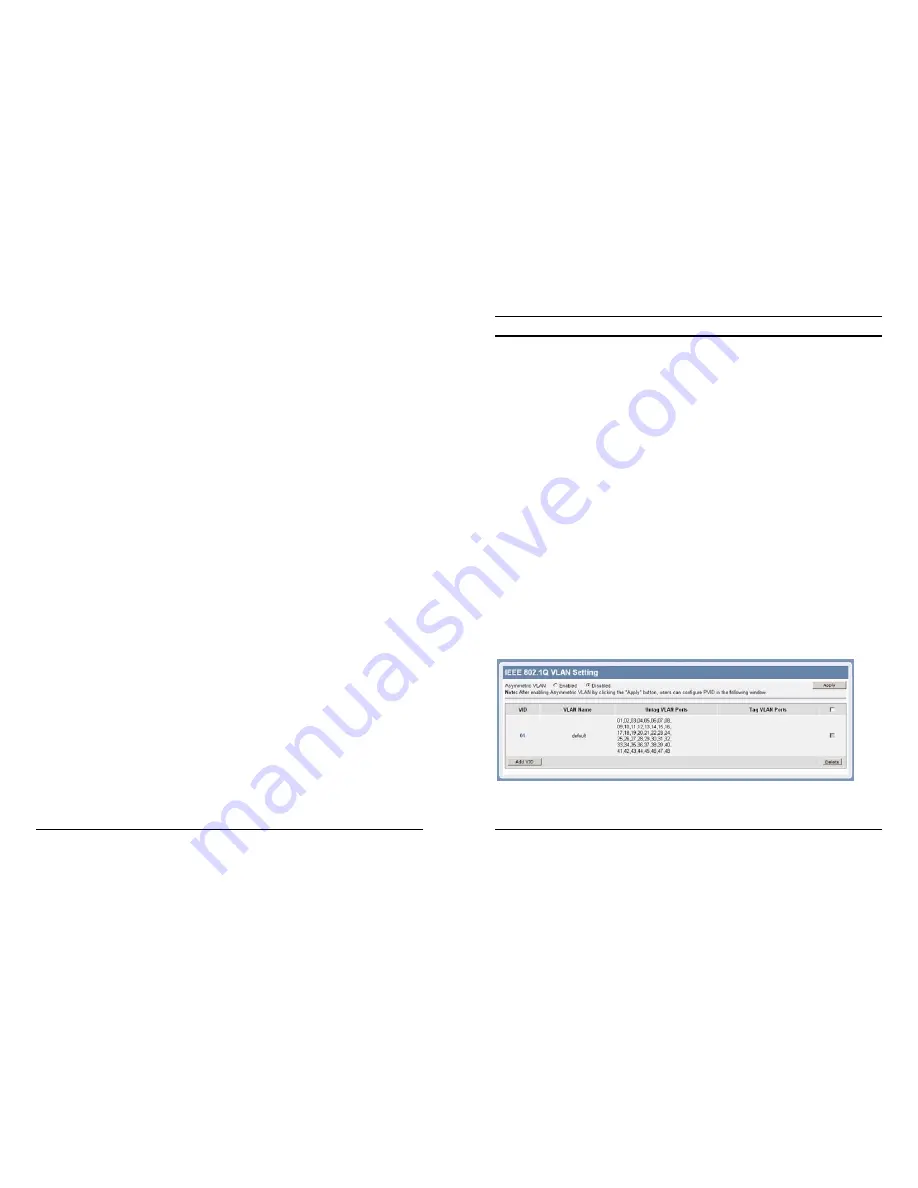
 

Asymmetric VLAN  

IEEE 802.1Q Asymmetric VLAN default setting is “Disabled”, you 
can press “Enabled” ratio button and Apply it to submit the 
Asymmetric VLAN function.  


Note: The settings of VLAN, IGMP Snooping and Forwarding table will be reset to 
default.


Summary of Contents for TEG-448WS - Switch

Page 1: ...equency energy If not installed and used in accordance with the instructions it may cause harmful interference to radio communications Operation of this equipment in a residential area is likely to ca...

Page 2: ...s not compromised c Mechanical Loading mounting of the equipment in the rack should be such that a hazardous condition is not achieved due to uneven mechanical loading d Circuit Overloading Considerat...

Page 3: ...ystem LEDs 12 Ports 1 48 Status LEDs 13 mini GBIC 45F 48F Status LEDs 13 Configuration 14 ii Installing the Web Management Utility 14 Discovery List 15 Monitor List 16 Device Setting 18 Toolbar 19 Con...

Page 4: ...iii Factory Reset 51 Backup Setting 51 Firmware Upload 52 System Reboot 52 Logout 53 Technical Specifications 54...

Page 5: ...trol and management objects but with a tenfold increase in theoretical throughput over 100 Mbps Fast Ethernet and a hundredfold increase over 10 Mbps Ethernet Since it is compatible with all 10 Mbps a...

Page 6: ...ng the CSMA CD Ethernet protocol Since the 100Mbps Fast Ethernet is compatible with all other 10Mbps Ethernet environments it provides a straightforward upgrade and takes advantage of the existing inv...

Page 7: ...i GBIC slots for optional mini GBIC transceiver to extend distance shared with 4 1000BASE T ports All RJ 45 ports support auto MDI MDIX Half duplex transfer mode for connection speed 10Mbps and 100Mbp...

Page 8: ...rong electromagnetic field generators such as motors vibration dust and direct exposure to sunlight Leave at least 10cm of space at the front and rear of the hub for ventilation 8 Install the Switch o...

Page 9: ...d 10 IDENTIFYING EXTERNAL COMPONENTS This chapter describes the front panel rear panel and LED indicators of the Switch Front Panel The figure below shows the front panel of the Switch Figure 4 Front...

Page 10: ...power cord into this connector Connect the male into a power outlet Supported input voltages range from 100 240V AC at 50 60Hz 12 UNDERSTANDING LED INDICATORS The front panel LEDs provides instant st...

Page 11: ...rk Off No link mini GBIC 45F 48F Status LEDs Link ACT On When the Link ACT LED is lit the port is successfully connected Blinking When the Link ACT LED is blinking the port is transmitting or receivin...

Page 12: ...ol version Shows the version of the Utility protocol z Product Name Shows the product name of the Switch z System Name Shows the system name of the Switch z Location Shows the location of the Switch z...

Page 13: ...der to receive Trap information the Switch has to be configured with Trap IP and Trap Events in the Web browser See Page 31 for more details 18 Add Item To add a device to the Monitor List manually en...

Page 14: ...View Log To show the event of the Web Management Utility and the device z Clear Log to clear the log In the Option TAB there are Refresh Time function this function helps you to refresh the time of m...

Page 15: ...screen will appear 22 Figure 15 System Information Configuration Menu When the main page appears find the Configuration menu in the left side of the screen Click on the setup item that you want to con...

Page 16: ...s the Refresh button 24 The Link Status in the screen will show the connection speed and duplex mode If there is no connection to the port down will be displayed Figure 16 Port Setting Note 1 Be sure...

Page 17: ...eflect department groups such as R D Marketing usage groups such as e mail or multicast groups multimedia applications such as video conferencing and therefore help to simplify network management by a...

Page 18: ...r Not Member A port can be Untagged in only one VID To save the VID group press Apply 28 VLAN Settings VID A unique VLAN ID VLAN Name A VLAN name can be setting as user wish Port The switch port numbe...

Page 19: ...g an untagged frame from the port the switch will assign a tag to the frame using the PVID of the port as its VID PVID settings Example 1 Here is an example of two VLAN groups with several ports in ea...

Page 20: ...ports member then apply settings 32 Example 2 802 1Q Asymmetric VLAN example Port 1 48 in VLAN1 port1 5 in VLAN2 port1 6 9 in VLAN3 All VLAN1 3 have access to Internet via port 1 Note The multi need...

Page 21: ...rt 6 48 to Not Member then apply settings Step 4 Create VID 03 and set port 1 port 6 9 to Untag port then apply settings 34 Step 4 Click on PVID settings change port 1 5 to PVID 2 and port 6 9 to PVID...

Page 22: ...which VLAN it belongs to If the receiving frame doesn t contain the tag header the switch will assign a tag to the frame using the PVID of the port as its VID Example 3 36 Step 1 Set VLAN1 port 1 to...

Page 23: ...function enables the user to cascade two or more devices t0 increase bandwidth The user can set up to six Trunk groups Enter a Trunking Name select the ports to be a member of the trunk and click Appl...

Page 24: ...Both transmit and receive mode this mode will duplicate both the data transmit from and data that send to the source port then it will forward to the sniffer port None mode this mode will not duplicat...

Page 25: ...time and fewer interruptions Maximum packet length supported is 9220 bytes 42 Advanced Setting Find that there are two items including IGMP Global Setting and IGMP VLAN Setting in Advanced menu IGMP...

Page 26: ...the loss of the last member of a group Default is 1 second Host Timeout 130 1225 sec This is the interval after which a learnt host port entry will be purged For each host port learnt a PortPurgeTime...

Page 27: ...sent the system information status on this screen it will show the Product Name Firmware Version Protocol Version MAC Address System Name Location Name IP Address Subnet Mask Default Gateway Trap IP L...

Page 28: ...Setting it allows Web Management Utility to monitor specified events on this Web Smart Switch By default Trap Setting is Disabled When the Trap Setting is Enabled enter the Destination IP address of t...

Page 29: ...fault password is admin If you forget the password press the Reset button on the front of the Switch Statistics The Statistics screen will show the status of each port packet count 50 Refresh To renew...

Page 30: ...store button Figure 29 Backup Setting Note when restoring a recorded file the current password will not be erased 52 Firmware Upload The Firmware Upload helps you to backup or upload firmware from to...

Page 31: ...bps half duplex 200Mbps full duplex Gigabit Ethernet 2000Mbps full duplex Topology Star Network Cables 10BASET 2 pair UTP Cat 3 4 5 up to 100m 100BASE TX 2 pair UTP Cat 5 up to 100m 1000BASE T 4 pair...

Page 32: ...ustomer an equivalent product to replace the defective item All products that are replaced will become the property of TRENDnet Replacement products may be new or reconditioned TRENDnet shall not be r...

Page 33: ...T EXIST OR WAS CAUSED BY CUSTOMER S OR ANY THIRD PERSON S MISUSE NEGLECT IMPROPER INSTALLATION OR TESTING UNAUTHORIZED ATTEMPTS TO REPAIR OR MODIFY OR ANY OTHER CAUSE BEYOND THE RANGE OF THE INTENDED...

Page 34: ......

Reviews: