background image

36

Threat Protection System Hardware Specification and Installation Guide

TPS fans

The 440T device includes five cooling fans (two of them are internal). The fans are not redundant or hot-

pluggable. If a failure to a fan module occurs, you must replace the entire device.
The 2200T device includes three cooling fans. The fans for the 2200T device are redundant but not hot-

pluggable. An individual fan can be replaced but not without first powering down the device.
The TPS Spare Fan (5066-3329) is a replacement unit and can only be used with TPS 2200T devices or

NGFW S3000/S8000 Series appliances.

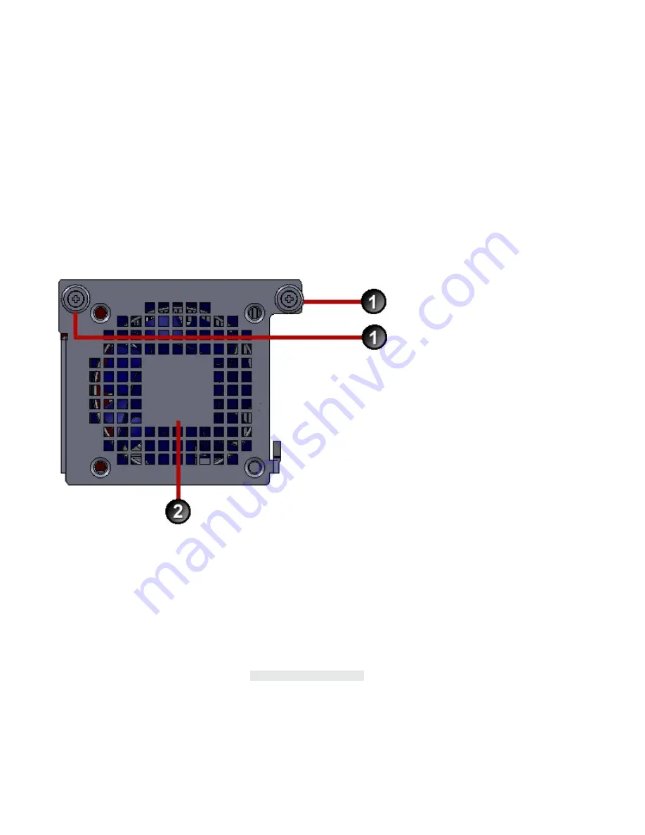
Figure 20. 2200T fan unit

1. Attachment Screws
2. Fan Assembly
When a fan module fails or its RPM rate falls below a certain threshold, the system generates a warning or

critical alarm message in its logs.
You can check a fan’s performance using:
• The Local Security Manager (LSM) graphical user interface: 

System Health > Monitor > Fan Speed

• The command line interface (CLI): 

show health fan

Replace the fan

Describes how to replace the fan.

Summary of Contents for TippingPoint 2200T

Page 1: ...Threat Protection System Hardware Specification and Installation Guide 5900 4108 December 2016...

Page 2: ...s are set forth in the express warranty statements accompanying such products and services Nothing herein should be construed as constituting an additional warranty Trend Micro Incorporated shall not...

Page 3: ...ices 4 Core hardware features 4 440T device 4 2200T device 6 TippingPoint 440T hardware description 8 Device overview 8 Chassis Front Panel 8 Chassis back panel 9 Chassis features 9 Power switch and p...

Page 4: ...and power supplies 17 External storage card 17 Ports 17 Model requirements 19 Power requirements 19 Cabling requirements 19 Technical specifications 19 Hardware installation and configuration 20 Inst...

Page 5: ...hernet connectors 31 Pluggable transceivers 31 Power supply and fan modules 33 The 2200T AC power supply 33 Connect the AC power supply 34 The 2200T DC power supply 34 Connect the DC power supply 34 T...

Page 6: ...iv Threat Protection System Hardware Specification and Installation Guide CFast card commands 40...

Page 7: ...maintaining TippingPoint security systems and associated devices Basic networking Network security Routing Related documentation A complete set of documentation for your product is available on the Ti...

Page 8: ...text typed at the command line Messages Messages are special text that is emphasized by font format and icons Warning Alerts you to potential danger of bodily harm or other potential harmful conseque...

Page 9: ...Threat Protection System Hardware Specification and Installation Guide 3 tippingpoint support trendmicro com Phone support North America 1 866 681 8324 International See https tmc tippingpoint com...

Page 10: ...se against network intrusion and provides application control The Threat Suppression Engine TSE scans detects and responds to network traffic according to the filters action sets and global settings m...

Page 11: ...Power supply One 350W built in System memory 16GB External CFast card 1 8GB Replaceable fans No High Availability HA Yes Zero Power High Availability ZPHA Built in ZPHA on the 8 copper ports In additi...

Page 12: ...M or centralized management through the Security Management System SMS 2200T device Figure 2 2200T device The 2200T device has the following hardware features Feature 2200T device Copper ports 8 1GbE...

Page 13: ...ZPHA module refer to TippingPoint Modular Fiber Copper ZPHA Installation Guide available on the TMC http tmc tippingpoint com In addition the device includes Built in intrinsic high availability featu...

Page 14: ...1 Prior to installation have the CLI Reference available for configuration information Device overview The 440T device is a small form factor device designed for smaller network environments in which...

Page 15: ...llustration shows a rear panel view of a 440T device Figure 4 440T device back panel 1 Fans 3 2 AC power supply 3 AC power connector 4 Power switch Chassis features The chassis features include the fo...

Page 16: ...current status of the software processes and the hardware Solid Green Both the hardware and the software processes are running normally Solid Yellow System is booting If the solid yellow indicator rem...

Page 17: ...following figure Figure 5 Management and Console ports 1 1 RJ 45 serial console port 2 1GbE copper management port 3 Activity LED 4 Link LED The management port LEDs indicate link and activity state...

Page 18: ...t the following requirements AC Voltage 100V 240V 4 2 amp 50 60 Hz Cabling requirements The 440T device ships with the following cables One AC power cable Null modem cable for the serial console manag...

Page 19: ...Operating Temperature 4 158 F 20 70 C Storage Altitude No degradation up to 10 000 feet 3048 m Humidity 5 to 95 non condensing External interfaces 1 1GbE copper management port 1 RJ 45 console port 8...

Page 20: ...e for configuration information 2200T device overview The 2200T device is a mid range system that has a larger form factor than the 440T device and is designed for network environments requiring inspe...

Page 21: ...SFP ports 3 1GbE copper ports 4 External CFast card 5 Dedicated HA port 6 ZPHA port 7 Console Management port 8 Power button 9 Alert indicator 10 System status indicator 2200T chassis back panel The f...

Page 22: ...ge 16 System status indicator on page 17 Alert indicator on page 17 Fans and power supplies on page 17 External storage card on page 17 Ports on page 17 Power button The power button is located on the...

Page 23: ...e status is undefined Flashing Yellow Hardware problem detected Software running normally Off Appliance power is off Fans and power supplies The 2200T device includes two power supplies and three cool...

Page 24: ...ment port 3 Link LED 4 Activity LED The management port LEDs indicate link and activity state as described in the following table LED Type Color Description Green Link is active at 1000Mbps Link Off L...

Page 25: ...power supplies are also available for the device Consult your TippingPoint account contact for more information if you require a DC power supply Cabling requirements The 2200T device ships with the fo...

Page 26: ...e 4 158 F 20 to 70 C Storage Altitude No degradation up to 10 000 feet 3048 m Humidity 5 to 95 non condensing External interfaces 1x1GbE copper management port 1x1 RJ 45 console port 8 1GbE copper por...

Page 27: ...page 28 Check LEDs on page 29 Run the setup wizard on page 29 Install the chassis Before installing your new security device gather any necessary materials and prepare the network and hardware site To...

Page 28: ...a 23 inch rack Bracket screws for attaching the brackets to the chassis Your device can be stored on a desktop on a shelf or in a rack If you are bolting the device to the rack follow these guideline...

Page 29: ...cket and ear 3 Secure the rack mounting brackets into the holes of the front rack post or mid rack post with three screws on each side rack screws not included in the kit Use Figure 10 on page 23 as a...

Page 30: ...rews not included in the kit on each side attach either the short slide bracket or the long slide bracket to the rear post of the rack depending on which length is needed to secure the chassis in the...

Page 31: ...unt for 2U chassis Describes how to mount a 2U TPS device in a two post rack You can choose to install your chassis into a two post rack using a front mount or a mid mount 1 Align the two front rack m...

Page 32: ...gure 14 on page 26 as a guide for how the front rack mounting brackets are attached to the appliance and to the rack in a front mount Use Figure 15 on page 26 as a guide for how the front rack mountin...

Page 33: ...ship with a slide rail kit to mount the appliance to a four post rack Slide rail kits are also available for order from TippingPoint Refer to the instructions in the slide rail kit for information abo...

Page 34: ...ion Describes how to attach the console port connection 1 Connect the RJ 45 null modem cable to the Console port on the front of the unit 2 Connect the other end of your cable standard sized female DB...

Page 35: ...g the ports you selected For more information about device network configuration and connections refer to the Local Security Manager User Guide and the CLI Reference Check LEDs When you connect power...

Page 36: ...on page 30 RJ 45 Ethernet connectors on page 31 Pluggable transceivers on page 31 RJ 45 COM console Describes the RJ 45 COM console specifications The following figure displays the RJ 45 connector and...

Page 37: ...is operating in 10Mbps 100Mbps mode Pin number Signal name 1 Transmit positive Tx 2 Transmit negative Tx 3 Receive positive Rx 4 Ground GND 5 Ground GND 6 Receive negative Rx 7 Ground GND 8 Ground GN...

Page 38: ...rom TippingPoint have been validated to achieve optimal performance with TippingPoint products Other vendor devices are not supported Using other vendor devices could be detrimental to proper operatio...

Page 39: ...ore than one power supply source All power sources must be removed to de energize the unit Note The 2200T device has removable fans and power supplies The power supplies are hot swappable It has no ot...

Page 40: ...If necessary power on the device with the button on the front of the chassis The 2200T DC power supply The 2200T device is NEBS compliant and can accept a combination of AC and DC power supply units...

Page 41: ...lug 3 Locate the power input terminal block on the back of the module 4 Attach the 12 AWG DC power wires to the power input terminal block labeled 48V and RTN The power wires should be crimped with l...

Page 42: ...ced but not without first powering down the device The TPS Spare Fan 5066 3329 is a replacement unit and can only be used with TPS 2200T devices or NGFW S3000 S8000 Series appliances Figure 20 2200T f...

Page 43: ...up slightly and partially pull it from its slot 3 Reach in the slot and disconnect the fan s cable connector from the main board 4 Remove the entire fan assembly from its slot 5 Set the faulty fan asi...

Page 44: ...ket on page 38 Installing and using the bracket on page 38 Removing the bracket on page 39 Power cord retention bracket Provides a description and image of the power cord retention bracket The power c...

Page 45: ...the chassis The spring loaded plunger in the center of the bracket slides into place Using the power cord retention bracket Follow this procedure to attach the power cord to the retention bracket 1 Fo...

Page 46: ...d other system data Caution Failure to properly remove the TippingPoint CFast card can result in disk corruption and a system error You can replace the CFast card when the system is operating Before y...

Page 47: ...lly user disk unmount Unmounts the card so that the user can remove it user disk encryption enable Encrypts the card if the system master key has been set Changing the encryption status reformats the...

Page 48: ...ey You are prompted to enter a master key that is between 9 and 32 characters in length contains a combination of numbers and uppercase and lowercase letters and that has at least one special characte...

Reviews: