


1/16 SLASH 4WD • 23
TUNING ADJUSTMENTS
the least traction and tend to spin up to extremely high RPMs. Higher
viscosity (thicker) oil causes the differential to act like a limited-slip
differential, distributing more equal power to the left and right wheels.
Your model will generally benefit from higher viscosity oil when
climbing, rock crawling, or racing on low-traction surfaces.
Note:
Heavier oil will allow power to be transferred even with one or more
tires off the ground. This can make the vehicle more likely to overturn.
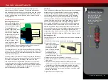
From the factory, both the differentials are filled with SAE 30,000W
viscosity silicone oil. Only use silicone oil in the differentials. Traxxas
sells SAE 10,000W and SAE 50,000W viscosity oil (see your parts list).
The differentials have to be removed from the vehicle and
disassembled to change/replace oil.
MOTOR AND GEARING
Extensive testing has been done to determine the best gear ratios
for the 1/16 Slash 4WD. The stock gearing balances power, speed,
and efficiency to optimize the performance of the model. However,
you may wish to try different gear ratios in order to customize the
performance of your model. The gearing chart on this page shows
appropriate gearing for the model.
By installing a pinion with fewer teeth, or a spur gear with
more teeth, the transmission’s final drive ratio is increased. This
means greater RPM is required to achieve a given speed. Using
a numerically higher gear ratio will increase torque, but reduce
top speed. Installing a pinion with more teeth, or a spur gear with
fewer teeth, will decrease the final drive ratio, which will generally
increase top speed but reduce torque. However, installing too large
a pinion will “overgear” the model, which will reduce performance
and may overheat the motor and speed control. Use the following
formula to calculate the overall ratio for combinations not listed on
the gear chart:
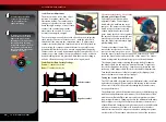
Motor Installation
To access the motor,
remove the gear cover
by removing the single
screw on the top of the
gear cover. The motor
uses an aluminum
mount for quick, easy
motor access and
gearing adjustment.
To remove the motor, first open the right battery door and slide
out the ESC. Next, remove the single large hex screw using the
supplied 2.5mm wrench. Then rotate the motor and mount to the
side of the model, and slide backward off the post.
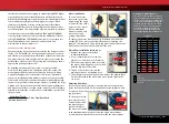
Pinion Gear Installation Instructions
1. Remove the motor as described
in Motor Installation.
2. Use a 1.5mm wrench to loosen the
pinion’s set screw. Remove the pinion.
3. Place the replacement pinion gear onto
the motor shaft. Align the set screw hole
with the flat side of the shaft.
4. Thread a 1.5mm set screw into the
pinion gear but do not tighten it yet.
5. Slide the pinion gear down the motor shaft so the wrench shaft
fits into the notch in the motor mount, as shown. Tighten the
set screw.
Adjusting Gear Mesh
Incorrect gear mesh is the most common cause of stripped spur
gears. Gear mesh should be checked and adjusted anytime a gear
is replaced. Access the gears by removing the single screw on the
top gear cover.
To set the gear mesh,
cut a narrow strip of
notebook paper and
run it into the gear
mesh of the motor.
The motor is mounted
to an aluminum motor mount. Loosen the single motor mount
screw with the provided 2.5mm wrench to slide the motor mount.
# Spur Gear Teeth
x 5.04 = Final Gear Ratio
# Pinion Gear Teeth
Motor Mount
Screw
Do Not Loosen
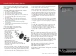
Gearing Compatibility Chart
The chart on the left shows a full range
of gear combinations. The stock ratio is
shown in green. The gear combinations
in red are not suitable when using the
included 6-cell battery, speed control,
and motor. These gear combinations
have been included in this chart as
they may be used with certain other
aftermarket equipment combinations.
Stock
Usable range
Not recommended with stock ESC, motor, and batteries
Does not fit
Spur Gear
Pinion Gear
45
50
55
16
-
-
-
17
-
-
-
18
-
-
15.40
19
-
-
14.59
20
-
-
13.86
21
-
-
13.20
22
-
11.45
12.60
23
-
10.96
12.05
24
-
10.50
11.55
25
-
10.08
11.09
26
8.72
9.69
10.66
27
8.40
9.33
10.27
28
8.10
9.00
9.90
29
7.82
8.69
9.56
30
7.56
8.40
9.24
31
7.32
8.13
8.94