


1/16 SLASH 4WD • 13
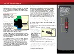
THE TRAXXAS TQ 2.4GHz RADIO SYSTEM
Remember, always turn
the transmitter on first and
off last to avoid damage to
your model.
When rechargeable batteries
begin to lose their charge,
they will fade much faster
than alkaline dry cells. Stop
immediately at the first sign
of weak batteries. Never turn
the transmitter off when the
battery pack is plugged in.
The model could run out of
control.
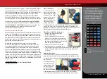
RADIO SYSTEM RULES
• Always turn your transmitter on first and off last. This procedure will
help to prevent your model from receiving stray signals from another
transmitter, or other source, and running out of control. Your model
has electronic failsafes to prevent this type of malfunction, but the
first, best defense against a runaway model is to always turn the
transmitter on first and off last.
• Always turn on the transmitter before plugging in the battery.
• Always use new or freshly charged batteries for the radio system.
Weak batteries will limit the radio signal between the receiver and
the transmitter.
Loss of the radio signal can cause you to lose control
of your model.
• In order for the transmitter and receiver to bind to one another,
the receiver in the model must be turned on within 20 seconds
of turning on the transmitter. The transmitter LED will flash fast
red, indicating a failure to link. If you miss it, simply turn off the
transmitter and start over.
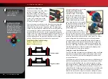
RADIO SYSTEM BASIC ADJUSTMENTS
Steering Trim
The steering trim knob located on the face of the
transmitter adjusts the neutral (center) point of the steering
channel. If your model pulls to the right or left when the
steering wheel is centered, turn the knob until the model drives
straight when the steering wheel is centered.
Channel Reversing
The TQ 2.4GHz transmitter has been programmed with the correct servo
direction settings for your model and should not require adjustment.
These instructions are for reference and troubleshooting only.
Reversing a channel reverses the direction of the corresponding servo.
For example, if you turn the steering wheel to the right and the model
turns left, Channel 1 would need to be reversed to correct the servo
direction. Use the following procedures to reverse the steering and
throttle channels, if necessary.
Servo reversing should only be required
if you accidentally reset the direction of a channel. Do not reverse the
steering or throttle channels unless necessary.
Steering reversing procedure:
1. Press and hold the SET button on the transmitter for two seconds.
The status LED will flash green.
2. Turn and hold the steering wheel to the full left or full right
position (it does not matter which position you choose).
3. While holding the steering wheel in position, press the SET button
to reverse the channel.
4. The channel is now reversed. Confirm correct servo operation
before running your model.
Throttle reversing procedure:
Note
: Throttle reversing is often times unnecessary on electric models,
as issues with the throttle can usually be solved by reprogramming the
speed control and/or verifying that the motor is wired correctly. Before
attempting to reverse the throttle channel using the procedure below,
you should first recalibrate the speed control. Refer to “
XL-2.5 Setup
Programming
” on page 16.
1. Press and hold the SET button on the transmitter for two seconds.
The status LED will flash green.
2. Move and hold the throttle trigger to the full forward or full brake
position (it does not matter which position you choose).
3. While holding the throttle trigger in position, press the SET button
to reverse the channel.
4. The channel is now reversed. Recalibrate the speed control and
then confirm correct servo operation before running your model.
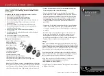
RADIO SYSTEM CONTROLS
Forward
Neutral
Brake/Reverse
TURN
R
IG
H
T
T
U
R
N
LE
FT
Make certain the model’s
receiver antenna is properly
installed before operating
your model. See “Installing
the Receiver Antenna.”
Failure to properly install the
receiver antenna will result in
greatly reduced radio range
and potential loss of control.
6
Always turn your
transmitter on first.
Turn on the model.
1
2
Plug in the battery.
3