background image

Page 10

Troubleshooting Steps

Printed 3/18/98

Travis Industries Pellet Stove Troubleshooting Guide (

 1994)

H

OPPER 

S

NAP 

D

ISK 

F

AULTY OR 

S

TOVE 

O

VERHEATED

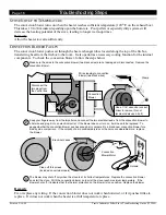
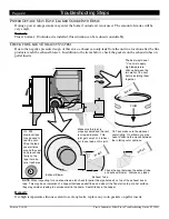
The hopper snap disk is a safety device that shuts off the auger if the hopper reaches an excessive temperature.
When the stove turns off unexpectedly the hopper snap disk may be faulty or the hopper may have reached an
excessive temperature.  The only way to check the hopper snap disk is to replace it with a new one and
monitor the heater's operation.

White/Blue 

Wire

Red 
Wire

610016

T-O-D 60T11

9312

L200-40F

Hopper 
Snap 
Disk

White/Blue and Red wires 
leading to hopper snap disk

The hopper snap 
disk is located 
on the left side 
underneath the 
hopper.

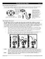
Replace the hopper snap disk and 
monitor operation of the heater over one 
hour on high to check this component.

To check the hopper snap 
disk, remove it and perform a 
continuity test.  It should  
show continuity until it is 
heated.  The convection 
snap disk should shut off 
continuity when it is heated 
to 200

°

 (6 to 10 seconds 

underneath a lighter).  You 
can also listen for a "click".

Heat the back 
side of snap disk 

Hopper Snap Disk

610016

T-O-D 60T11

9312

L200-40F

Remedy

If the heater works correctly after one hour on high with the new hopper snap disk, the hopper snap disk was
probably faulty.  If the heater shuts down, first make sure the convection blower stayed on when the stove
reached its highest temperatures.  If the convection blower turned off, the heater probably overheated and the
hopper snap disk shut the heater off (go to the section "Convection Blower May Be Faulty").  If the
convection blower works correctly, yet the heater shut off, the heater is overheating for some reason.  This
could be due to pellets piling up the feed tube, heater placement, lack of air for the convection blower, or other
factors.  Call Travis Industries for information on a remedy for this situation.

A

UGER 

N

OT 

P

RIMED

The first time you start your heater, 

or

 if you completely run out of pellets, the auger will need to be primed.

Remedy

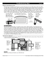
Turn the heater on, press the start button, and turn the BURN RATE to "HIGH".  This will allow the pellets
to feed up the auger and start to fall into the firepot before you start the heater.  After this "priming" the stove
can be started normally.  If this does not work, go on to the next step.

Summary of Contents for 400 PI

Page 1: ...lower Convection Snap Disk Auger Tube Convection Blower Heat Exchanger Tubes Air Control Control Box Auger Motor Firepot Air Inlet Ash Traps System Snap Disk Hopper Snap Disk Flow Switch Igniter COVERS AVALON 900 PS PI LOPI FOX FIRE 400 PS PI 10850 117th Place N E Kirkland WA 98033 1994 ...

Page 2: ...let is blocked 21 Power Outage May Have Leaked Smoke Into Home 22 Check for Leaky Exhaust System 22 Igniter Faulty 23 Airwash Faulty 23 Check for Vibration Noisy or Loose Components 24 REMOVAL INSTRUCTIONS Accessing Internal Components on Stoves 25 Accessing Internal Components on Inserts 26 Auger Motor 27 Auger Tube 28 Auger Flight 28 Hopper 29 Air Inlet 30 Air Control 30 Exhaust Blower and Exhau...

Page 3: ...me was Smothered or the Pellets Blew Out 9 Hopper Snap Disk Faulty or Stove Overheated 12 Damaged or Exposed Wiring 17 Convectionblowerdoesn t distributehotair Stove Not up to Temperature 18 Convection Blower Faulty 18 Convection Snap Disk Faulty 19 Damaged or Exposed Wiring 17 Flameislazyorsooty or pelletspileupinfirepot Air control too far in 19 Stove needs cleaning 20 Air leak 21 Pellets are po...

Page 4: ...use this guide This guide is intended for Travis Industries dealers and service personnel Because of the inherent danger in working with heating appliances all work must be done by qualified service personnel Know how to switch out components quickly Most of the procedures in this guide require a component to be switched out and the stove tested This allows for quick diagnostics and simple compone...

Page 5: ...compare their performance Test the Stove Adequately Before leaving a customer s home make sure to operate the stove for at least one half hour Use the time to clean up or finish paperwork Furthermore test the stove on various burn rates to insure proper operation Monitor the Stove s Performance Become familiar with how a brand new stove performs Everything from the flame quality blower noise and v...

Page 6: ...nconsistent electrical flow If the fuse has blown more than once in a month we suggest that the entire wiring of the stove be inspected for any damage that might have caused a short Any exposed wire should be covered or replaced immediately Remedy Replace the fuse with a 5 amp quick blow fuse There are two fuses taped to the inside of the control box To access remove the control box and take off t...

Page 7: ...electrical circuits run through the switch box making its operation crucial to nearly every aspect of the heater s operation On stoves the switch box is removed by removing two screws with a 5 16 nutdriver On inserts the switch box clips into place on the left side The best way to check the switch box is to switch out the switch box Hook up a new switch box and check to see if this fixes the probl...

Page 8: ... System Snap Disk Located behind the convection blower Make sure the back of the snap disk comes in contact with the exhaust box bend the snap disk holder if necessary Problem 2 The heater shuts off 5 to 15 minutes after starting Remove the system snap disk and perform a continuity test When it is heated to 120 3 to 10 seconds underneath a lighter continuity should be shown betwen the center and l...

Page 9: ...t of air to burn properly This requires the proper air control setting and a properly maintained system With too little air the flame will smoother with too much air the pellets will blow out of the burnpot In both cases the stove becomes cool enough to shut down and pellets pile up into the feed tube The above problems may cause the pellets to pile up inside the firepot eliminating good air flow ...

Page 10: ...near the vent termination locations near hills or lakes or local wind patterns Wind Rain Cap make sure it is not pressed on too far reducing the outlet area Pellet Vent Sections check for creosote accumulation which indicates a poorly burning stove Tee s are recommended over elbows because they come with removable clean out covers which speed vent cleaning considerably Make sure to clean off the s...

Page 11: ...y in front of the exhaust box This is the passageway between the exhaust duct and exhaust box Clean the inside of the exhaust box Firepot Feed Tube Exhaust Duct Exhaust Box The exhaust gasket must form an air tight seal between the exhaust box and exhaust blower 3 First hotwire the exhaust blower to see if it pushes air If uncertain about performance place the exhaust blower in a location outside ...

Page 12: ... can also listen for a click Heat the back side of snap disk Hopper Snap Disk 610016 T O D 60T11 9312 L200 40F Remedy If the heater works correctly after one hour on high with the new hopper snap disk the hopper snap disk was probably faulty If the heater shuts down first make sure the convection blower stayed on when the stove reached its highest temperatures If the convection blower turned off t...

Page 13: ...und to dislodge stuck pellets Hopper Lid Five phillips head screws hold the hopper cover in place the front two are inside the hopper HOPPER COVER FRONT For inserts the hopper cover may need to be removed to check for caught debris If pellets are allowed to pile up the feed tube the auger may become jammed Feed Tube Auger Tube Feed Tube Pellets pile up and jam at the top of the auger tube Pay clos...

Page 14: ...t rotates along with the auger shaft and may be pointing a different direction You may need to remove the motor stop and gently turn the auger by hand to expose the lock screw do not force it this will strip the auger motor gearing If the auger does not turn when hotwired remove the auger motor and check the following To check if the auger motor is working correctly remove it from the heater and h...

Page 15: ...aft The lock screw holds the auger motor to the auger shaft If it is not aligned correctly and tightened the auger will not turn Auger Motor Lock Screw 3 On Pre 1993 Models the two allen set screws are used instead of the Lock Screw See Appendix 3 for details NOTE Drive Collar Remedy 1 Use a 3 16 allen wrench to loosen the screw that holds the auger motor in place 2 Find the flat portion of the ou...

Page 16: ...en suction is applied the flow switch will need to be replaced 4 Check the pellet vent system for clogging If the pellet vent is clogged or restricted the flow switch will shut the power to the auger off Nipple for Tubing Check the two electrical connections Mounting Bracket Disconnect the two wires leading to the flow switch and jump them If the heater works correctly follow the directions below ...

Page 17: ...hat pass near the auger motor are not loose they may become caught on the lock screw and become dislodged Make sure the wires do not touch the exhaust tube exhaust box or firebox back if they come in contact with these hot components they may melt and short out on the chassis NOTE White Red Black Blue Brown Gray White Red Red White Blue White Yellow Brown Green Black Black White Control Box Switch...

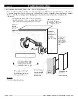
Page 18: ...hotwire and plug it into an electrical outlet If the blower does not turn on it will need to be replaced To gauge whether the convection blower pushes enough air compare it to a brand new convection blower for a side by side comparison If the velocity of air is considerably less or the noice considerable more replace the blower 1 2 Make sure the wires to the convection blower two black wires are n...

Page 19: ...irepot and check the flame Ideally the pellets should be agitating slightly with an occasional ember flying up and a bright jagged yellow flame È If the pellets aren t moving and no embers are jumping out of the firepot and the flame is dark orange with black tips see drawing A below pull the AIR CONTROL out 1 2 Check again È If the pellets are moving vigorously with many burning pellets jumping o...

Page 20: ...re to remove all flyash from the ledge directly in front of the exhaust box This is the passageway between the exhaust duct and exhaust box Firepot Feed Tube Exhaust Duct Exhaust Box Pry the clean outs out with a screwdriver Exhaust Ducts This area is often overlooked because it is difficult to access Make sure to remove all flyash from this area Test tube brushes work well for this type of cleani...

Page 21: ...lowing two pages demonstrate how to check for air leaks NOTE Stoves installed on pedestals require the bolts used during shipping to be replaced in the front corners of the firebox otherwise air will enter the firebox from this area Check for air leaks around the perimeter of the door and ashpan Air leaks are best detected by running a lit match or lighter around the perimeter of the door and ashp...

Page 22: ...ate a worn or flattened gasket Either replace the gasket or loft up the gasket so it seals against the face of the stove Air leaks detected around the ashpan indicate a loose ashpan latch or worn gasket If the ashpan handle does not have any resistance when it is twisted to secure the ashpan the latch will need to be tightened see the instructions below Ashpan handle Ashpan Pawl To tighten the paw...

Page 23: ...s of pellets before you purchase a large amount Burn the pellets in your pellet heater and check for these signs of bad pellets clinkers develop in the air holes on the bottom of the firepot the auger jams for no apparent reason and when the hopper is cleaned out the auger runs again there is more than one half cup of sawdust in the bottom of the bag of pellets or the pellets don t burn well on a ...

Page 24: ...On Tee s make sure the cleanout seals tightly On elbows you may need to silicone the cracks between the rotating outer sections U L 324 aluminum tape may be used to seal the vent Wrap the tape several times around the vent and press down firmly on the tape to make sure it adheres Exhaust Tube Check the seal between the exhaust tube and exhaust blower Silicone any leaks The best way to seal L vent ...

Page 25: ...ical Leads with male quick connects Heating Element Sheath Mounting Hole Mounting Bracket Air Hole The heating element starts to glow after 3 minutes Remedy Replace the igniter AIRWASH FAULTY The airwash must be set correctly for the glass to remain clean The steps below detail airwash adjustment and inspection Airwash Blade Firepot Screw Ashlip Airflow The airwash blade should be approximately 1 ...

Page 26: ...ound Panel Brass Trim Double back tape If a blower is creating noise try loosening its connection re aligning the gasket and re tightening the connection If the auger motor clicks check to see if it is knocking against the motor stop If this is happening attach a piece of gasket tape between the auger motor and motor stop Make sure the rubber tipped leveling bolts are screwed out far enough to sup...

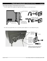
Page 27: ...push in and turn 1 4 turn clockwise To release rotate 1 4 turn counter clockwise The rear access panel of the stove is removed by unscrewing the 11 screws that hold it in place Remove the 11 screws that hold the rear access panel in place Rear Acces Panel To remove the strain relief use a pair of slip joint pliers to press from the top and bottom of the relief Pull the relief out once it becomes l...

Page 28: ...alon inserts the panels are lifted up Lopi inserts require the ashlip to be removed Ð see the owner s manual for instructions Unclip this to remove Exhaust Blower Horizontal exhaust duct Remove the clip first Always replace the clip after re installing 7 16 Wrench Vertical exhaust duct Exhaust Tube Exhaust Duct Clip Exhaust Duct Clips Flyash access panel remove wingnuts to access A bolt holds the ...

Page 29: ... until it is easy to access 3 16 Loosen the lock screw until the auger motor can be pulled free Disconnect the two quick connects leading to the auger motor NOTE This dimple must line up with the lock screw when re installing Pull the auger motor from the drive collar Drive Collar 4 On inserts elevate the rear of the insert at least 3 Use a 7 16 wrench to remove the two bolts that hold the motor g...

Page 30: ... Jammed Augers that are extremely jammed may not be freed by this method In these cases remove the auger motor and manually turn the auger flight use an allen wrench inserted into the lock screw or a pipe wrench on the drive collar If this does not work remove the hopper and try to dislodge pellets with the hopper upside down If this does not work remove the auger flight following the directions b...

Page 31: ... to the side The hopper may require slight twisting to remove the auger clamp tube from the feed tube on the stove 900 PI Foxfire 400 PS and Foxfire PI 1 Remove all pellets from the hopper Remove the vertical exhaust adapter 2 Disconnect all wiring leading to the auger motor hopper snap disk flow switch and control box both molex plugs Disconnect the flow switch tube from the flow switch Detach al...

Page 32: ... inlet bracket with hose clamps Air Control Flow Switch Combustion air inlet 7 16 Wrench Standard Screwdriver AIR CONTROL The air control adjusts the amount of combustion air that enters the firepot 1 Remove the convection blower 2 See the illustration below for instructions on removing the air control components Flex Hose The air control spacer is held in place by the air control inlet tube Hose ...

Page 33: ... Also check the exhaust gasket to make sure it seals the exhaust blower to the exhaust box 900 PI and Fox Fire Bay 1 Remove the vertical exhaust duct from the insert 2 Pull the insert out of the fireplace to access the right side Follow the directions below Remove these four nuts with a 3 8 nutdriver Hopper If this nut can not be reached with a nutdriver it may be loosened by inserting a wrench th...

Page 34: ...nvection Blower 4 The blower is removed by swinging it inwards and sliding it out see the illustration below When replacing the blower make sure the gasket is intact and the clamp is correctly oriented CONTROL BOX INCLUDES FUSES 1 Access the left side of the heater 2 Disconnect the two molex connectors that attach to the side of the control box 3 Remove the two screws that attach the control box w...

Page 35: ...trol box Remove these screws with a phillips screwdriver to open up the switch box Phillips Screwdriver HOPPER CONVECTION AND SYSTEM SNAP DISKS 1 Access the left side of the heater 2 Remove the convection blower this is not necessary to access the 900 PS hopper snap disk 3 The snap disk is removed from its holder with a phillips screwdriver System Snap Disk Convection Snap Disk Hopper Snap Disk on...

Page 36: ...er FLOW SWITCH FLOW SWITCH TUBE FLOW SWITCH NIPPLE The flow switch flow switch tube and flow switch nipple work together to sense negative pressure inside the exhaust box If no pressure is sensed at the flow switch it will disable the auger motor 1 The flow switch is located at the rear left of the heater and is held in place with two screws use a 5 16 nutdriver on all models except the 900 PS whi...

Page 37: ...k must be connected as shown below NOTE This illustration depicts the molex connector for the wiring harness The numbers are added for reference only and do not appear on the actual connector DOOR A door with an old or damaged gasket will leak air into the firebox causing decreased performance Check the door gasket to make sure it compresses against the face of the heater when the door is shut The...

Page 38: ...r see the illustration below for each component s location and appearance Air Exhaust System Consists of Purpose Possible Problems Air Inlet Flex Hose Provides air for combustion Flex Hose crushed or blocked Air Control Adjusts the amount of air going to the firepot Adjusted incorrectly or does not slide in and out all the way Firepot Holds pellets during combustion Firepot holder is on incorrectl...

Page 39: ...t tube and exhaust vent Switch Box Determines the convection blower speed Faulty rheostat the component next to the label FAN replace box and check Electronic Safety System Consists of Purpose Possible Problems Hopper Snap Disk Turns the heater off for overheating Faulty component replace component and check Flow Switch Turns the heater off for blocked vent or exhaust blower failure Faulty compone...

Page 40: ...10520 1294 91 1 Yr St 5708 1294 93 1 Yr Vert Exh Duct Left Side Ins 11003 11405 1294 92 1 Yr Ins 15005 15895 1294 91 1 Yr Vert Exh Duct Left Side Ins 11406 1294 93 1 Yr Ins 15896 17654 1294 92 1 Yr Vertical Exhaust Duct St 2500 3017 1295 91 1 Yr Ins 17655 1294 93 1 Yr Vert Exh Duct Right Side St 3018 4121 1295 92 1 Yr St 2501 3790 1295 91 1 Yr Vert Exh Duct Right Side St 4121 1295 93 1 Yr St 3803 ...

Page 41: ...s 10003 0592 91 1 Yr Ins 15005 0592 91 1 Yr Switch Box Bracket 2 Pc Ins 10003 0593 91 N A Ins 15005 0593 91 N A Fuse 5 Amp For Control Boxes St 4300 1792 93 N A St 5900 1792 93 N A Fuse 5 Amp For Control Boxes Ins 11406 1792 93 N A Ins 17700 1792 93 N A Wire Harness St 1002 1501 0500 90 1 Yr St 1005 1867 0500 90 1 Yr Wire Harness St 2500 0501 93 1 Yr St 2501 0501 93 1 Yr Wire Harness Ins 10003 050...

Page 42: ...0293 90 1 Yr Ins 15005 17825 0293 90 1 Yr Auger Bearing Upper Lower Ins 11605 0293 93 1 Yr Ins 17826 0293 93 1 YR Exterior Parts Door Glass All 1491 A90 1 Yr All 1005 1491 90 1 Yr Glass Gasket All 1492 90 N A All 1493 90 N A Door Gasket And Ashpan Gasket Set All 1391 90 N A All 1391 90 N A Air Control Knob Black Phenolic St 1002 1300 90 1 Yr St 1005 6335 2057 82 1 Yr Air Control Knob Black Phenoli...

Page 43: ...t 5 Not Used Post 6 Post 7 GOES TO New Airotronics Timing Block Post 1 Post 2 Splice Wire Post 3 Post 5 Post 2 Splice Wire Auger Timing Block see the illustration below Wire Attached to ACP 646 Timing Block Post 1 Post 2 Post 3 Post 4 Post 5 Post 6 Not Used Post 7 Not Used GOES TO New Airotronics Timing Block Post 4 Post 1 and 2 Splice Wire Post 3 Post 8 Post 9 START UP TIMING BLOCK AUGER TIMING B...

Page 44: ...ews On earlier models this attachment was done with two set screws One set screw holds the drive collar to the auger shaft This set screw goes through the drive collar and attaches to the auger shaft The other set screw connects the output shaft of the auger motor to the auger shaft It goes through the collar and connects to the dimple of the output shaft If the second set screw is not in correctl...

Page 45: ...The orientation of the wires except for system snap disk does not matter when attaching to the components The system snap disk must be connected as shown below NOTE This illustration depicts the molex connector for the wiring harness The numbers are added for reference only and do not appear on the actual connector WIRING HARNESS DIAGRAM FOR 1991 AND 1992 MODELS NOTE White Red Black Blue Gray Whit...

Page 46: ......
Page 47: ...Green Brown Green Yellow Red White Black Black White 1 2 3 4 5 6 7 8 9 10 11 12 1 2 3 4 5 6 7 8 9 10 11 12 1 2 3 4 5 6 7 8 9 10 11 12 13 15 14 1 2 3 4 5 6 7 8 9 10 11 12 1314 15 Switch Box Molex Connector Numbers correspond to the pins shown here Startup Timing Block Auger Timing Block Hot Common Wiring Harness Molex Connector Numbers correspond to the pins shown here Start Switch Burn Rate Potent...

Page 48: ...n blower while it is running Attach piecing points to the multimeter probes and pierce the two wires running to the convection blower On HIGH the multimeter should read 110 120 volts the same voltage as the outlet On LOW the multimeter should read 60 70 volts The LOW voltage is adjusted by turning the pot inside the rheostat housing The HIGH voltage can not be adjusted If the voltage does not fall...

Page 49: ...eck between the two electrical connections With the flow switch idle there should be no continuity While providing suction on the tubing you should have continuity The flow switch should be replaced if it does not react in this manner Altitude Considerations for the Flow Switch The flow switch monitors the pressure in the exhaust system The pressure in the firebox on our pellet heaters is approxim...

Page 50: ...towards the heater See Non combustibles for more information Combustion Air Intake The tubing used to attach outside air for combustion to the pellet appliance It must not be made of combustible materials P V C tubing can not be used Required for mobile home installations Combustion Blower See Exhaust Blower Control Box The control box is the aluminum box that contains the timing blocks that contr...

Page 51: ...otor from spinning Non combustible Materials that will not ignite when subjected to flame for extensive time Includes steel iron brick tile concrete slate asbestos glass plaster or any combination thereof If there is uncertainty as to the construction of a wall or ceiling assume it is combustible Drywall is combustible Output Shaft The output shaft is the shaft extending from the auger motor that ...

Page 52: ...Exhaust Tube insert 26 Exhaust Tube stove 31 Fan see Exhaust Blower or Convection Blower Feed Tube troubleshoot 7 Feed Tube 29 Firepot troubleshoot 7 Five Most Common Problems 37 Flex Hose removal 30 Flex Hose troubleshoot 21 Flow Switch Incl tube nipple removal 34 Flow Switch technical info 47 Flow Switch troubleshoot 14 Flue restricted 8 Fuse Blown On Control Box troubleshoot 4 Fuses see control...

Reviews: