6
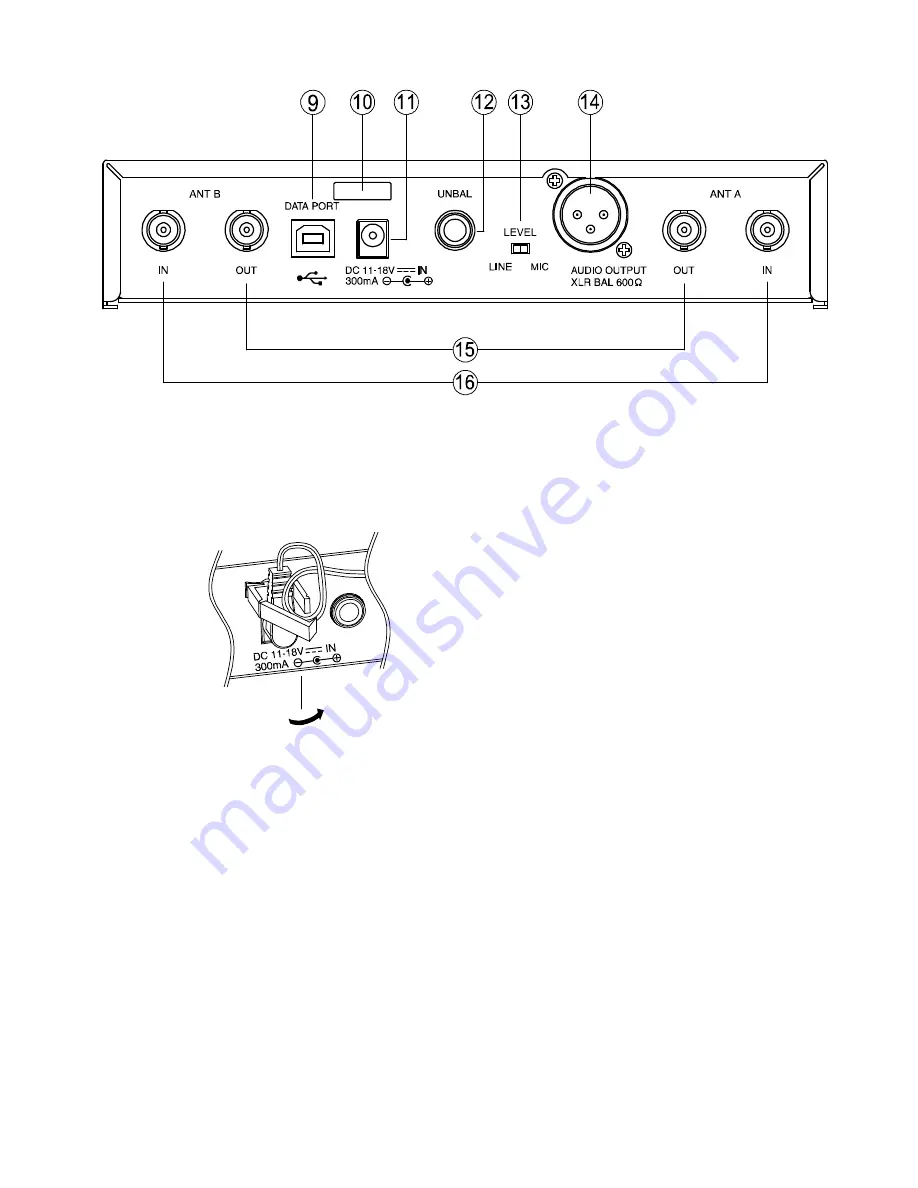
[Rear]
9. USB port
Used to connect the unit to a PC with the
installed software.
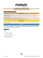
10. Cable hanger
Hook the power cable onto this part.
11. DC input jack
Connect the power cable of the supplied
AC adapter to this jack.
12. AF output
Unbalanced 1/4” jack socket, male type
+9 dBm (maximum)
13. AF output
level selector
Sets the output level from the AF outputs by
selecting either MIC or LINE
14. AF output
MIC / LINE selectable, balanced, XLR
connector, male type
LINE level : +15dBm (maximum)
MIC level : -25dBm (maximum).
15. Antenna distribution outputs A, B
50 ohm, BNC
Output the same signals as those which are
input to Antenna inputs A, B. Used for an RF
cascade connection.
16. Antenna inputs A, B
50 ohm, BNC
Phantom powering for the external antenna
(optional)
For the wireless system covering a relatively
narrow area, use the supplied two rod antennas,
which should be set up at 45° outwards from
a vertical line.


