background image

Table of Contents

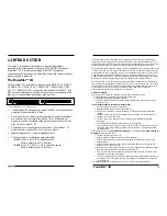
1 INTRODUCTION . . . . . . . . . . . . . . . . . . . . . . . . . 1

The PowerStar™ III  . . . . . . . . . . . . . . . . . . . . . . . . . . . . . . . .1
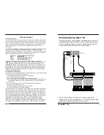
Networking the PowerStar™ III  . . . . . . . . . . . . . . . . . . . . . . .2
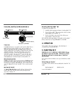
Connectors, Switches, and Status Indicators  . . . . . . . . . . . . .3

2 SITE CONSIDERATIONS. . . . . . . . . . . . . . . . . . . . 4

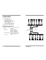
3 INSTALLATION. . . . . . . . . . . . . . . . . . . . . . . . . . . 5

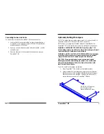
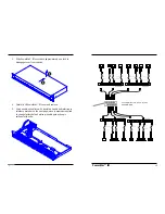
Unpacking PowerStar™ III . . . . . . . . . . . . . . . . . . . . . . . . . . .5
Setting Pin Jumpers  . . . . . . . . . . . . . . . . . . . . . . . . . . . . . . . .6
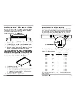
Installing PowerStar™ III in Rack or on Table  . . . . . . . . . . . .9
Setting Twisted Pair Polarity Switch  . . . . . . . . . . . . . . . . . . .10
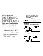
Connecting Link Cable to Host  . . . . . . . . . . . . . . . . . . . . . .11

Connecting Twisted Pair Link Cable  . . . . . . . . . . . . . . . . . . . .11
Connecting Twinax Link Cable  . . . . . . . . . . . . . . . . . . . . . . . .13

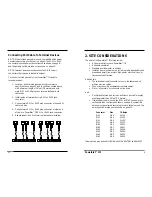
Connecting Port Cable to Terminal Devices  . . . . . . . . . . . .15
Powering the PowerStar™ III  . . . . . . . . . . . . . . . . . . . . . . . .16

4 OPERATION . . . . . . . . . . . . . . . . . . . . . . . . . . . . 16
5 MAINTENANCE . . . . . . . . . . . . . . . . . . . . . . . . . 16

POLICY AND PROCEDURE

. . . . . . . . . . . . . . . . . . . . . . . . . 17

CABLE SPECIFICATIONS

. . . . . . . . . . . . . . . . . . . . . . . . . . . . 19

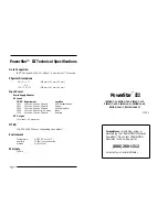
POWERSTAR™ III TECHNICAL SPECIFICATIONS

. . . . . . 21

i

19

PowerStar™ III

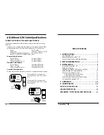
AS/400 and S/36 Cable Specifications

Twisted Pair Cable and Connector Specifications

The physical characteristics of the twisted pair cable must meet or exceed the
following:

Category 3 wire or better is required; category 5 wire is recommended. Either
shielded twisted pair (STP) or unshielded twisted pair (UTP) can be used. 

Gauge

26 to 22 AWG

Attenuation 

Less than 11.5 dB @ 5-10 MHz

Differential Characteristic Impedance 

85 -110 

@ 10 MHz 

DO NOT USE FLAT OR “SILVER SATIN” WIRE.

Minimum Cable Distance:

Host to Product

7.6 meters (25 feet)

Product to Product

7.6 meters (25 feet)

Product to Terminal Device

7.6 meters (25 feet)

Maximum Cable Distance:

Host to Product

762 meters (2500 feet

)

Product to Product

762 meters (2500 feet

)

Product to Terminal Device

762 meters (2500 feet

)

Connector Characteristics:

Twisted pair connection requires one active pair configured as straight through. 

When using RJ-11 connectors, the
active pair can be pins 2 & 5 or pins 3
& 4.

When using RJ-45 connectors, the
active pair can be pins 1 & 2, pins 4 &
5 or pins 3 & 6.

1

6

Top View
of the
RJ-11 Cable
Connector

1  2  3  4  5  6

Thick lines
indicate
pairs

Thin lines
indicate
pin leads

1

6

Crossview
of the RJ-11
Cable Connector

Top

1  2  3  4  5  6  7  8

Top View
of the
RJ-45 Cable
Connector

Thick lines
indicate
pairs

Thin lines
indicate
pin leads

1

8

Crossview
of the RJ-45
Cable Connector

Top

1

8

Summary of Contents for PowerStar III

Page 1: ...r AS 400 Controllers Physical Dimensions 8 6 x 6 x 1 7 219 mm x 153 mm x 43 mm OR 17 0 x 7 5 x 1 7 432 mm x 191 mm x 43 mm Input Power Power Supply Adapter AC Input TN PN Requirement Location 3500 120 volts 60 hertz 28 watts USA Canada Mexico 3501 230 volts 50 hertz 28 watts Europe 3506 240 volts 50 hertz 28 watts United Kingdom 3508 100 volts 50 60 hertz 28 watts Japan 3510 240 volts 50 hertz 28 ...

Page 2: ...s Der Anschluss dieses Gerätes an ein öffentlickes Telekommunikationsnetz in den EG Mitgliedstaaten verstösst gegen die jeweligen einzelstaatlichen Gesetze zur Anwendung der Richtlinie 91 263 EWG zur Angleichung der Rechtsvorschriften der Mitgliedstaaten über Telekommunikationsendeinrichtungen einschliesslich der gegenseitigen Anerkennung ihrer Konformität Twinax Cable and Connector Specifications...

Page 3: ...ded twisted pair STP or unshielded twisted pair UTP can be used Gauge 26 to 22 AWG Attenuation Less than 11 5 dB 5 10 MHz Differential Characteristic Impedance 85 110 Ω 10 MHz DO NOT USE FLAT OR SILVER SATIN WIRE Minimum Cable Distance Host to Product 7 6 meters 25 feet Product to Product 7 6 meters 25 feet Product to Terminal Device 7 6 meters 25 feet Maximum Cable Distance Host to Product 762 me...

Page 4: ...d shipping incurred if after testing a return is classified as No Problem Found TN s total liability in connection with the products and their installation to all persons and from all causes in the aggregate whether in contract tort or strict liability shall not exceed the amount paid to TN for the product directly related to the alleged damage However in no event shall TN have any liability to a ...

Page 5: ...OT MAKE AND DISCLAIMS ALL OTHER WARRANTIES EXCEPT TITLE EXPRESSED OR IMPLIED INCLUDING BUT NOT LIMITED TO ANY WARRANTY OF DESCRIPTION MERCHANTIBILITY FITNESS FOR A PARTICULAR PURPOSE OR NON INFRINGEMENT AND ANY WARRANTY BASED UPON PRIOR WRITTEN OR ORAL REPRESENTATIONS REGARDING SUCH PRODUCTS MADE BY TN ITS EMPLOYEES AGENTS OR REPRESENTATIVES B Limitations and Exclusions If the customer believes an...

Page 6: ... provided on the 7 port PowerStar III two Link host connectors are provided on the 14 port PowerStar III These connectors each provide an RJ twisted pair link to AS 400 or S 3x host signals Seven 7 or fourteen 14 terminal device connectors labeled 0 1 2 3 4 5 or 6 provide RJ twisted pair connection for distributing the AS 400 or S 3x host signals to terminal devices AT BACK PowerStar III models wi...

Page 7: ... 2 3 4512 RJ 45 2 1 3 4521 RJ 45 3 6 3 4536 RJ 45 6 3 3 4563 RJ 45 4 5 3 4545 RJ 45 5 4 3 4554 Same active pins as used in IBM baluns P Ns 69x7883 and 96x6187 Connecting Port Cable to Terminal Devices NOTE When twisted pair cable is used compatible baluns must be selected according to the chart on page 4 the RJ 11 or RJ 45 connector pin settings must be configured as shown on page 8 and the polari...

Page 8: ...ices Connect the PowerStar III to power Direction is provided in the pages that follow Unpacking the PowerStar III The PowerStar III packing contents should include the following Item Part Number PowerStar III PSIII 1 7 11 PSIII 1 7 45 PSIII 1 7 11 T PSIII 1 7 45 T PSIII 2 14 11 PSIII 2 14 45 PSIII 2 14 11 T PSIII 2 14 45 T Power Supply Adapter 3500 3501 3506 3508 or 3510 depending upon power conf...

Page 9: ...ge precautions when setting pin jumpers Use needle nosed pliers with insulated handle Failure to observe this caution could result in circuit board failure To verify or modify the jumper pin settings 1 Place PowerStar III on table or other stable surface 2 Using medium Phillips screwdriver remove three 3 screws that secure cover to PowerStar III left side three 3 screws that secure cover to PowerS...

Page 10: ...engage cover from chassis 4 Carefully lift PowerStar III cover and remove 5 Using needle nose pliers with insulated handle and referring to reference material on the next page move jumpers as required to change factory default active pin settings to active pin settings for the site ...

Page 11: ...er host to the PowerStar III using either twisted pair or twinax cable NOTE All cable lengths must be greater than 25 feet 7 6 meters Connecting Twisted Pair Link Cable When installing twisted pair cable attach a balun to the AS 400 or S 3x twinax port then attach the twisted pair cable between the balun and the RJ Link connector on the PowerStar III CAUTION Do NOT use a balun to connect twisted p...

Page 12: ... PowerStar III is installed on a table top or other flat surface Failure to observe this caution could cause the PowerStar III to overheat and could result in data transmission failure and or equipment damage Setting Twisted Pair Polarity Switches There are two sets of polarity switches at the 14 port PowerStar III front one set for the left controller or host port and seven device ports and one s...

Reviews: