
PowerStar™ III
8
11
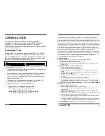
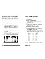
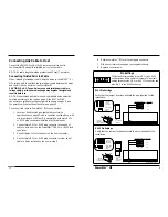
RJ-11 Pin Settings
Verify that the jumper locations activate the pins required for the
installation.
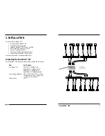
RJ-45 Pin Settings
Verify that the jumper locations activate the pins required for the
installation.
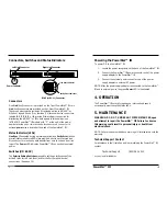
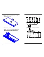
6. Rotate PowerStar™ III cover to rest again on chassis.
7. Slide cover forward to engage cover against chassis.
8. Replace cover screws.
1
6
Top View
of the
RJ-11 Cable
Connector
1 2 3 4 5 6
Thick lines
indicate
pairs
Thin lines
indicate
pin leads
1
6
Crossview
of the RJ-11
Cable Connector
Top
2,5
3,4
1,6
PowerStar III Jumpers
PowerStar III Top Front
RJ-11 Pins
NOT USED
1 2 3 4 5 6 7 8
Top View
of the
RJ-45 Cable
Connector
Thick lines
indicate
pairs
Thin lines
indicate
pin leads
1
8
Crossview
of the RJ-45
Cable Connector
Top
3,6
4,5
1,2
7,8
PowerStar III Jumpers RJ-45 Pins
NOT USED
1
8
PowerStar III Top Front
Pin Settings
The default factory setting for both RJ-11 and RJ-45
configurations is two centered jumpers. This default
setting activates pins 3 & 4 in the RJ-11 connector and
pins 4 & 5 in the RJ-45 connector.
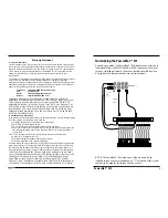
Connecting Link Cable to Host
Connect the AS/400, Sys36, or 5x94 remote controller host to
the PowerStar III using either twisted pair or twinax cable.
NOTE: All cable lengths must be greater than 25 feet (7.6 meters).
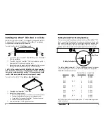
Connecting Twisted Pair Link Cable
When installing twisted pair cable, attach a balun to the AS/400™ or
S/3x twinax port, then attach the twisted pair cable between the balun
and the RJ Link connector on the PowerStar III.
CAUTION: Do NOT use a balun to connect twisted pair cable to
twinax cable. A mid-link media change may degrade the signal and
result in data loss.
NOTE: When twisted pair cable is used, compatible baluns must be
selected according to the chart on page 4, the RJ-11 or RJ-45
connector pin settings must be configured as shown on page 8, and
the polarity switch must be set as shown on page 10.
To connect link cable to PowerStar™ III link connectors:
1. Locate or build twisted pair cables that conform to
specifications on page 23 and to conditions noted above, with
minimum length of 25 feet (7.6 meters) and with male RJ-11
or RJ-45 plug connectors installed at both cable ends.
2. Connect male RJ-11 or RJ-45 plug connector at one end of
cable to a Link port on the PowerStar™ III RJ-11 or RJ-45 jack
connector.
3. Connect balun to the twinax port on the host computer.
4. Connect male RJ-11 or RJ-45 plug connector at other end of
cable to balun installed on the host in step 3.


