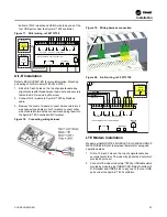


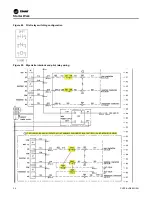
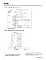


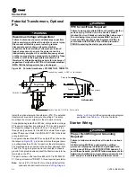


Figure 51. Autotransformer interlock and pilot relay wiring
Starter Work
CVRF-SVN005C-EN
37
Starter Sub-Panel Installation
Virtually all Symbio™ UCP2 panel upgrades will have the
starter sub panel installed as a direct replacement of the
existing UCP2 starter module.
The starter module LLID, and CTs and any turn-down
transformers can be mounted on the sub- panel.
The starter control conversion will provide a direct replacement
of the existing UCP2 starter module. For UCP2 installations it
is recommended that the existing CTs and PTs will be reused
and mounted on the Symbio™ starter sub-panel.
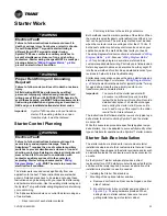
Installation steps are as follows:
1. Remove existing UCP2 module keeping potential
transformers and secondary current transformers if
needed for reuse.
2. Install existing potential transformers on lower panel if
required and secondary current transformers if needed on
the bracket.
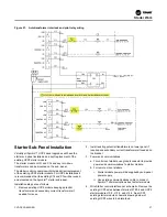
3. Power and communications.
a. For unit mount starters, use global connector to provide
power and communications to starter module.
b. For remote mount starters
i. Starter module power will be supplied by sub-panel
power supply.
ii. Use existing communications cable to connect
Symbio™ communications bus to starter module.
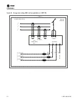
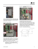
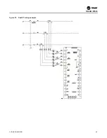
4. Wire Starter control interface per schematic. Remove the
existing UCP2 wires between terminal 2TB1-6 and UCP2
starter module J10-3, J12-3, and J14-3. See UCP2
existing starter module schematic drawing below of
existing UCP2 wires to be discarded.


