8
rev.
JDAC0160A(H)
JDWC0160A(H)
SERIAL No.
JUAC0160A(H)
JUWC0160A(H)
TENS.
400V/3Ph+N/50Hz
AUX.
24
VOLT
NO. TENS. (V)
OA (A) [/1]
FLA (A) [/1] LRA (A) [/1] P (kW) [TOT]
COMPRESSOR
1
400/3
9,5
14,8
87
4,53
FAN
2
230/1
2,9
3,5
4
0,63
HUMIDIFIER
1
230/1
9,4
0,0
0
2,16
HEATERS STD
1
230/1
8,7
0,0
0
6
ENHANCED HEATERS
1
400/3
13,0
0,0
0
9
UNIT (STD HEATERS) (*)
18,1+5,8x1Ph
11,79
UNIT (ENHANCED HEATERS) (*)
22,5+5,8x1Ph
14,79
UNIT (STD CAP max) (*)
18,1+5,8x1Ph
12,26
UNIT (ENH. CAP max) (*)
22,5+5,8x1Ph
15,26
Icu=15kA (CEI EN 60947-2) / (*) in operating conditions at 400V
Icu=15kA (CEI EN 60947-2) / (*) in operating conditions at 400V
TSR
STOP:
310 °C
MAN. RESET
TSRA
STOP:
328 °C
MAN. RESET
AP
STOP:
38,7 bar
MAN. RESET
BP
STOP:
4,6 bar
DIFF:
2 bar
CHARGE:
R410A
kg/circ.
PRECHARGE: DRY NITROGEN N2
J
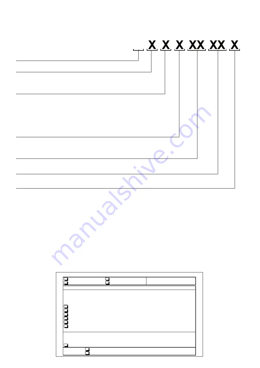
Identifying prefix of the Jupiter family
Air discharge
U = Upflow (upwards discharge)
D = Downflow (downwards discharge)
operating typology
C = Chilled water units
A = Air cooled direct expansion units
W = Water cooled direct expansion units
Fan typology
V = Radial Electronically Commutated fans
C= Centrifugal fans
MODELS
the code which distinguishes the models is composed of 4 characters:
IDENTIFICATON PLATE
The air conditioner can be identified by the plate which is placed in the electrical panel of the machine. The model and
any eventual accessories which are installed are indicated by an “X” in the corresponding box
the plate carries the following data:
•
Model and series number of the machine.
•
type of power supply.
•
Power absorbed by the unit and the single components.
•
Current absorbed by the unit and the single components.
•
the set points of the cooling circuit pressostatic valve and safety valve.
•
type of refrigerant.
•
Loading or pre-loading of each cooling circuit.
number of compressors
indicative cooling capacity
Power supply voltage
A = 400 V / 3Ph (+N) / 50 Hz
B = 230 V / 1 Ph / 50 Hz
FAC-SIMILE


