51
Installazione
Funzionamento
Manutenzione
Unità ad alta precisione Jupiter
Unità a espansione diretta
JDAC / JUAC / JDAV / JUAV / JDWC / JUWC / JDWV / JUWV
Taglie: 0115 – 0125 – 0133 – 0135 – 0150 – 0160
Unità ad acqua refrigerata
JDCC / JUCC / JDCV / JUCV
Taglie: 0020 – 0025 – 0030 – 0040 – 0060
PKG-SVX24B-IT
PROBLEM
POSSIBLE CAUSE
CHECK/CORRECTIVE ACTION
ABSent or LoW Air
FLoW
A) there is no power to the fans.
Check the power supply to the fans
B) The filter is blocked (possible intervention of
the dirty filters alarm).
1) Shake the dust out of the cartridge and clean
with a vacuum cleaner. Replace the filter if it is
completely blocked.
2) Check the correct setting of the dirty filter
pressure switch PFS.
C) Fans rotating in the wrong direction.
reverse input phases and check if fans are
rotating in the correct direction
D) The air flow is obstructed.
Check paragraph “Air DiStriBUtion”
e) the fans’ thermal protection intervenes.
Check the resistance of the fan motor windings.
re-set then measure the voltage and absorption.
F) Fan speed regulator not set correctly.
See paragraph FAn SPeeD ADJUStMent AnD
SPeeD reGULAtor SettinG.
G) excessive head loss in the air distribution
sistem.
1) Check the dimensioning of the air distribution
system, as well as all its parts (ducts, suspended
ceilings, floor plenum, air grilles)
2) (For tDCr and tUCr models - having fans
with backward curved blades) change the power
supply voltage of the fans, in order to increase
the fan rotation speed.
PROBLEM
POSSIBLE CAUSE
CHECK/CORRECTIVE ACTION
interVention oF
one or BotH oF tHe
eLeCtriCAL HeAterS’
SAFetY tHerMoStAtS
A) There is insufficient air flow.
See “LACK oF / ABSent Air FLoW”.
B) the thermostat connection wire is interrupted Check the continuity of the connection of the
safety thermostats to the control system.
C) one or both of the thermostats are broken
replace one or both of the electrical heaters’
safety thermostats
55
53
54
55
53
54
4
52
51
4
52
51
ACCESSORIES
Humidifier
U2
U1
U6
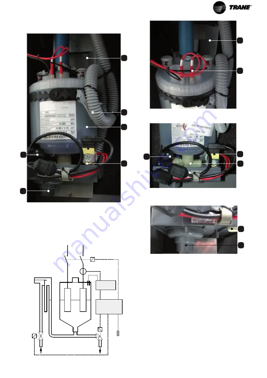
U1 Boiler cylinder
U2 Water supply tray
U3 High water level detector electrodes in the boiler
cylinder
U4 Condenser drain
U5 Collector charge/discharge
U6 Water input
U7 Drain
U8 Feed water solenoid valve
U9 Boiler cylinder electric drainage valve
U10 Overflow pipe (behind the cylinder)
U11 Amperometric transformer for measuring the current
(within the electrical panel)
U12 Humidifier interface board (inside the electrical
panel)
U13 Microprocessor control board
U14 temperature and humidity probe
U9
U9
U8
U3
U2
MANUALE D'USO E MANUTENZIONE
CONDIZIONATORI D'ARIA DI PRECISIONE
(32)
Rev 1.5. – 27-02-2004 IT
32
UMIDIFICATORE
COMPONENTI DEL SISTEMA
Su richiesta l’unità di condizionamento può essere dotata di un umidificatore a elettrodi immersi (versioni D e H). Il gruppo di produzione del
vapore si compone dei seguenti organi.
Fig. 11 a
1.
Scheda di interfaccia umidificatore:
SIU
;
( interna al quandro elettrico ) .
2.
Trasformatore amperometrico per la misura
dell’intensità ( interna al quandro elettrico ).
di corrente assorbita dal cilindro vapore
TAM
;
3.
Vaschetta di carico dell’acqua di alimentazione;
4.
Elettrodi di alto livello dell’acqua nel cilindro
vapore;
5.
Tubo di sfioro del troppo pieno ( DIETRO AL
CILINDRO);
6.
Cilindro ebollitore (o cilindro vapore);
7.
Elettrovalvola dell’acqua di alimentazione:
EVC
;
8.
Elettrovalvola di drenaggio del cilindro ebollitore:
EVS
.
9.
Scheda del controllo a microprocessore:
mP20
;
10.
Sonda di temperatura ed umidità:
STU
;
8
3
4
6
7
U2
U
10
U8
U14
U9
U1
U11
U3
U12
U13
U4
U8
U7
U5
U7


