


21
Installazione
Funzionamento
Manutenzione
Unità ad alta precisione Jupiter
Unità a espansione diretta
JDAC / JUAC / JDAV / JUAV / JDWC / JUWC / JDWV / JUWV
Taglie: 0115 – 0125 – 0133 – 0135 – 0150 – 0160
Unità ad acqua refrigerata
JDCC / JUCC / JDCV / JUCV
Taglie: 0020 – 0025 – 0030 – 0040 – 0060
PKG-SVX24B-IT
J*AC - J*AV
0151
0251
0331
0351
0501
0601
Recommended minimum size
Model
CAP0251 CAP0251 CAP0331 CAP0361
CAP0511
CAP0661
Max external air temperatur
°C
46
42.5
44.2
43.2
44.5
44.2
J*WC -J*WV
0151
0251
0331
0351
0501
0601
Recommended minimum size
Model
RAL0360 RAL0360 RAL0360 RAL0510
RAL0700
RAL0700
Max external air temperatur
°C
45
45
43
43
45
43
Installation
WARNING! The laying of the lines and the
refrigerant connections must be carried out by
a qualified refrigerant circuit technician.
the refrigeration circuit must be connected to the condensing
unit with copper pipes. the diameter of the pipes must be
chosen according to the length of the refrigerant line itself
(preferably less than 30 m) therefore it is possible that the
internal diameter of the valves supplied by trAne will not
coincide with the diameter of the pipes.
Conforming to the Standards en 14276-1 and en 14276-2
the minimum recommended thickness for the gas supply
pipe where bends are made for the air cooled units with
r410A refrigerant, must be equal to the values present in the
attached table below. the value `r’ refers to the minimum
allowed radius of the bend.
111
I
GB
LINEA DI MANDATA
DISCHARGE LINE
-5
0
5
10
15
20
25
30
35
40
Lunghezza equivalente [m]
3 - Non consentito - Unacceptable
2 - Consentito - Acceptable
1 - Ideale - Recommended
DP/L = 14
DP/L = 12
DP/L = 10
DP/L = 8
DP/L = 7
DP/L = 6
DP/L = 5
DP/L = 4
DP/L = 3
DP/L = 2
DP/L = 1
In conformità alle norme EN14276-1 e EN14276-2 lo spessore minimo
raccomandato per le tubazioni della linea di mandata del gas dove sono
praticate delle curve per le unità condensate ad aria con refrigerante
R410A deve essere pari ai valori presenti nella tabella sotto allegata. I
valori R si riferiscono ai raggi di curvatura minimi consentiti.
Conforming to the S tandards EN14276-1 and EN14276-2 the minimum
recommended thickness for the gas supply pipe where bends are made
for the air cooled units with R410A refrigerant, must be equal to the values
present in the attached table below. The value ‘R’ refers to the minimum
allowed radius of the bend.
Diametro esterno - External Diameter
Raggio di curvatura - Radius of the Bend
Spessore - Thickness
De (mm)
28
100
1,2
22
66
1
18
27
1
16
26
1
12
20
1
De
r
t
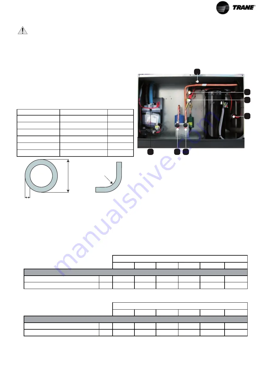
During the installation of the cooling unit, a solenoid
valve should be fitted on the liquid line between the inner
unit and the external condenser, to avoid malfunctioning
and to protect the compressor from unwanted liquid
migration during start- up.
G?
G3
G2
G?
G6
G7
U
to connect the refrigerating circuit to the condensing unit
proceed as follows:
•
check that the diameter of the connections corresponds
to the diameter of the pipes to be connected. if
necessary use suitable copper reductions;
•
weld the piping coming from the condensing unit to the
connections of the air conditioner respecting the inlet
and outlet directions of the refrigerant.
note: with external temperatures of less than -10°C the
use of condensers for low temperatures is recommended:
cap Lt optional.
Remote Dry coolers
External diameter Radius of the bend Thickness
De (mm)
r [mm]
t [mm]
28
100
1,2
22
66
1
18
27
1
16
26
1
12
20
1
Remote air cooled condensers
Recommended minimum size
Recommended minimum size
Model
C°
C°
Model
Max external air temperature
Max external air temperature


